TAPE 78/AI/07 (Side one)
THIS TAPE HAS BEEN RECORDED ON APRIL 27TH 1979 AT 13 AVON DRIVE BARNOLDSWICK. THE INFORMANT IS STANLEY GRAHAM WHO WAS THE ENGINEER AT BANCROFT MILL AND WHO HAS BEEN THE INTERVIEWER ON MOST OF THE TAPES..
Bancroft Folio, engine pictures number 014 and 015. Neg numbers 777231 and 777230
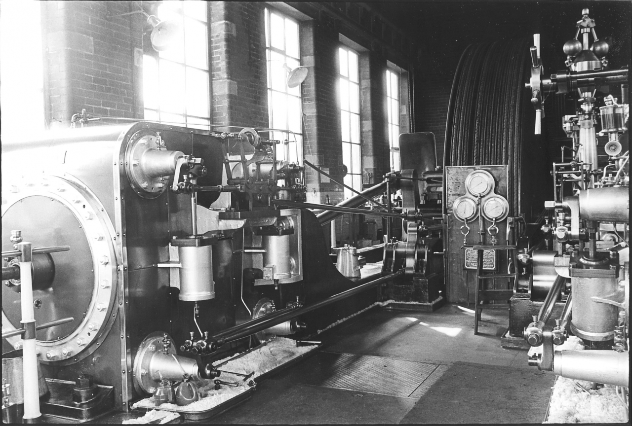
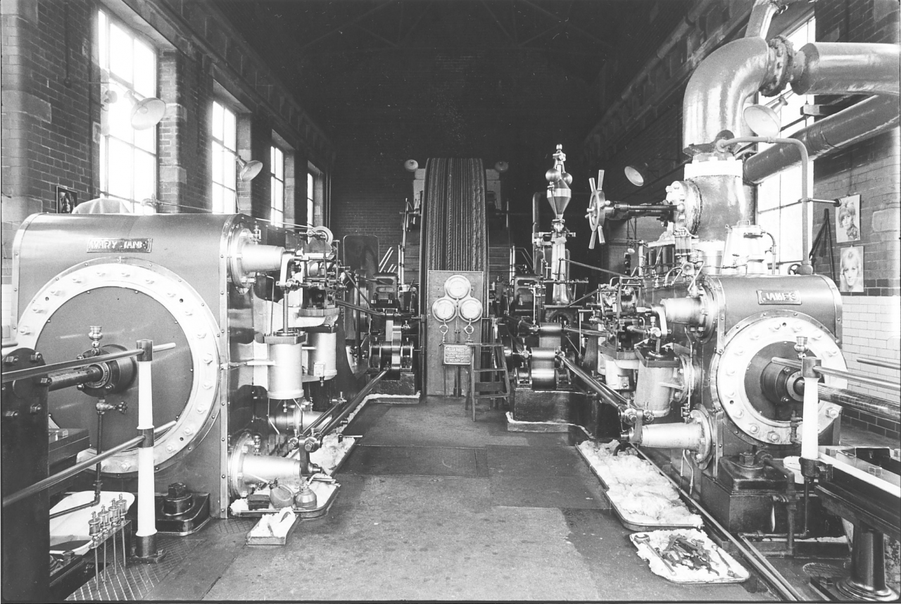
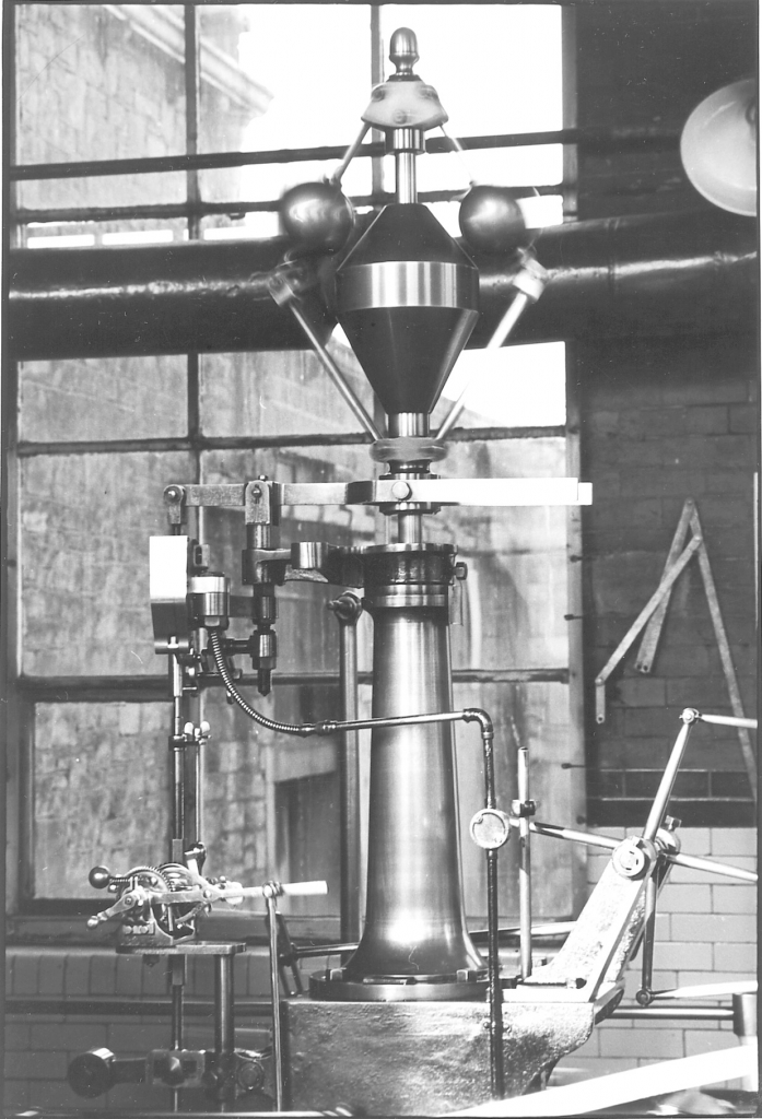
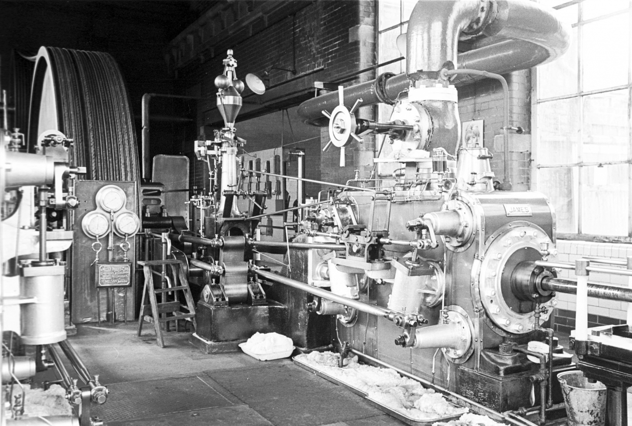
I’m continuing now with the description of the two pictures numbers 14 and 15 in the Bancroft Folio. On picture 14, if you look on the low pressure bed just in front of the cylinder, you will see a large tin, actually it's a two gallon stainless steel tin. This contains the reserve supply of cylinder oil for the engine. The cylinder oil came in 40 gallon barrels, and cylinder oil is of such a consistency that it requires to be warm before it can be used easily. What I used to do was have two of these tins always full of oil, one them on top of the high pressure cylinder where it warmed up slowly. And another one in reserve on the low pressure engine bed. This was mainly because it was just as easy to carry two tins as one when you were filling them up. It meant that the chore of fetching oil from the top end of the engine house only had to be done about once every two or three days instead of once a day perhaps. There was also a kettle of oil set in a custom made depression in the insulation on top of the high pressure cylinder. This was very hot and so poured easily. The kettle was original equipment with the engine and fitted exactly into the aperture.
Looking at picture 15 you get a good view of the whole of the engine, down the inside of each cylinder. You can see the fish tank oilers on the flywheel shaft and the smaller, but similar oilers on each side of the second motion pulley at the end of the house. Notice the patch of white painted on the wall behind these. This was to make it easier to see the flow of oil into the bearing when you were going round checking the oils. If you look carefully at the left hand aquarium on the flywheel you can see, in the bottom window, the middle of the three oil oilers dropping oil into the bearing. You could see at a glance whether oil was running or not. This wasn’t a drip feed, there was a solid flow from each orifice into the bearing and an equal flow back from the pump.
You’ll notice that the top window of the aquarium is black. This indicates that the oil level is above the top of the overflow pipe. In other words the pump is delivering oil back faster than the oilers are taking it. This tells you that the pump is operating properly. I always kept the oil level high enough to support this condition as this was a fail safe device. Supposing you made a mistake and the oil feeds were turned off. You might have forgotten to turn them on at the start up, strangely enough, you might turn the oils off when you went to inspect them. The process of checking the oils became automatic and occasionally the brain switched off and you actually went into shutting down mode instead of oil checking mode. This has happened to me when I was distracted for some reason. The fail safe us that if this happens, as long as you have sufficient oil in the system, the overflow will lubricate the bearing even if the taps on the main oil feeds are turned off.
It’s very difficult to see on this picture but there was a pipe coming out of the fish tank oiler which dripped oil into small cups on top of the eccentric sheaves. This is quite unusual, these sheaves were usually greased, but on the Bancroft engine they were oil lubricated and the oil ran down into a trough below and thence back into the tank from which it was pumped back up into the fish tank. So these sheaves were being lubricated all day with a constant supply of fresh oil which was a good thing. I say a good thing but you had to be careful not to allow too much feed. It didn’t matter too much on the low pressure side but on the high pressure side the eccentric sheaves are next to the three cotton driving ropes for the governor. If there was too much oil dripping in these sheaves it could splash out on the ropes. They became soaked in oil and cotton ropes don’t like this. It encourages them to come to pieces and slacken. The governor ropes were soaked in oil when I took over and had to be replaced by Kenyons from Dukinfield who did any rope work we needed.
You can see that there are two ropes missing on the flywheel; reading from the left they are number 1 and number 5. From time to time ropes have been replaced on this flywheel and evidently someone felt that there was no need to replace those two. Quite properly because the engine wasn't delivering it’s full horse power for many years due to the fact that there wasn’t a full complement of looms in the mill. Bear in mind that each of these ropes is quite capable of delivering 50hp so 11 ropes coped comfortably with our load which was a maximum of 400hp.
In front of the flywheel can be seen the polished steel stand carrying three large gauges and the makers nameplate which you can read quite easily, William Roberts & Sons - Engineers and Millwrights - Phoenix Works – Nelson, Lancashire. This firm of course is now defunct, it went out in about 1948 I think when it was bought out by another company and the works closed down. In point of fact I think I'm right in saying that they made their last steam engine in about 1926 and these were exported to India. Actually they were some of the biggest engines that they ever made. Roberts weren't one of the big makers but they were a very good firm. The only fault with Roberts engines really was the fact that the steam valves only had single ports. This is a bit technical but I have decided that in these descriptions I shall give quite a lot of detail. If I go beyond your capacity to take it in just gloss over the technicalities. [As I digitise these tapes in 2003 I am conscious of the fact that I shall die soon and all this knowledge will be lost so please bear with me if I get a bit long winded. Remember that I will not tell you anything unless I believe it to be true.]
Right, single ported valves. This means that the valves had one large slot in them which coincided with a single slot in the port machined in the cylinder casting. This slot is the aperture through which steam is allowed to enter the engine. When you are setting the valves on a steam engine you have to decide how much ‘cover’ you are going to allow them to have when the valve is closed and at rest. It is this cover or overlap on the seat that actually closes the valve. It is the difference between the point where the edge of the valve shuts the steam off and the position it reaches when at rest.
If you think about the valve when it is closed it is held down on the seat by the steam pressure bearing down on it. If you think about a port size on Bancroft engine of say 16 square inches this means that at 140psi there is a force of 2,240lbs in old measurement, this is a ton bearing down on the valve. Imagine the friction between the face of the valve and the valve seat with a ton bearing down on it. This is not impossible to move, if properly lubricated the valve can be moved quite easily by use of the valve key when starting the engine. However, this cover has quite a significant effect on valve timing. Newton Pickles and I were in complete agreement that the engine ran best with the least cover possible. Most text books will recommend cover of up to ¼ of an inch on an engine of this size and some authorities even more. I used to aim for about a sixteenth of an inch. The way to set it was to open the valve with the valve key and listen for the point when the steam entered the cylinder. You can then alter the linkage until you have the position right.
So we now understand cover. The point about single port and double ported valves is that a double ported valve can be run with less cover than a single ported engine because by doubling the amount of surface available to the valve the events can be much shorter and retain accuracy. Burnley Ironworks engines had double ported valves and were always regarded as very good engines which ran well.
Picture number 016. Negative number 770300.
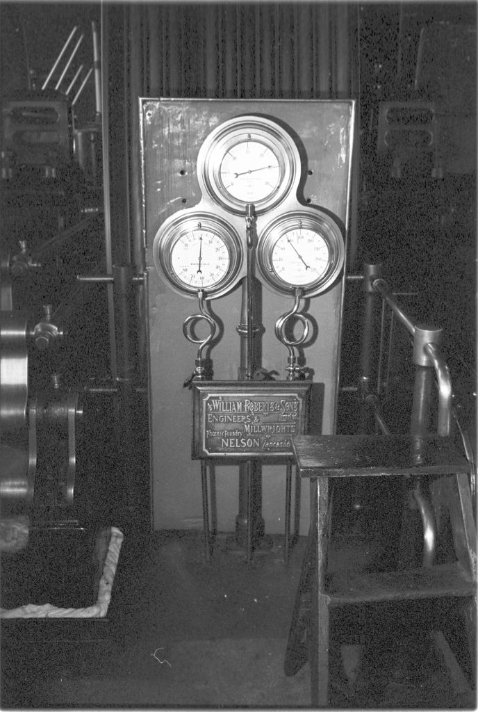
I’m still talking about picture 15 but as I describe the gauges mounted in front of the flywheel you might profit from looking at picture 16 which is a close-up of them.
The first thing to notice is that behind the gauges there is a backing plate that has one or two misplaced holes in it. This is not an original fitment, I fitted it to catch the small pieces of rope dressing that flew off as the flywheel was rotating and this plate stopped them being thrown back on to the engine. I’ll admit that I was probably more profligate in the use of rope dressing than my predecessors because I thought it did so much good and it may be that I was the first engineer to be troubled by flying grease.
This plate tells a story of its own. It was made of blued steel and the edges are protected by small bore brass pipe which has been split and fitted on to the edge. The original splash plates at the cranks are made in exactly the same way. It was a very common construction used by tinsmiths when making this type of guard or tray. This particular item was in fact originally used as a floor plate under a Barber Coleman knotting machine. Bancroft used to have two of these but one had been discarded and I found this plate in the cellar. It was exactly the size and shape I wanted so I used it behind the gauges.
Right, the gauges themselves. These three gauges gave the engineer essential information on how the engine was running. The picture was taken whilst the engine was running on a normal day with about 300hp load. I can tell this simply by looking at the readings.
The top gauge is showing the vacuum that the air pump is pulling measured in inches of mercury. It’s reading 23 ½ “ of mercury which isn’t a bad reading at all considering what a bad air pump we had. A good reading would be 25” or slightly more. The condition of the air pump isn’t the only factor that governs the amount of vacuum you can pull. Atmospheric pressure has a bearing on it as well. If you consider atmospheric pressure it can vary between 28 ½ “ of mercury and 30 ½ “, a variation of about 10%. This influenced the efficiency of the air pump. Another factor was the temperature of the condensing water which was being drawn in from the lodge. The warmer the water, the less efficient the pump. This used to be a big problem in summer where more than one mill was sited on a watercourse as the top mill was sending warm water down to the ones below. Therefore the best conditions were in winter when we had a bright clear frosty day with high atmospheric pressure. At times like these the vacuum was over 25”. Incidentally atmospheric pressure and air temperature influenced combustion in the firetubes of the boiler as well. Cold air at high pressure meant that the chimney could pull a better draught and draw a greater weight of air through the fire giving better combustion and a hotter fire. In the old days when we had coal fires at home we all knew this, in winter when the fire in the grate burned white hot we would say that it was ‘burning frost’.
Notice that the cock on the pipe to the vacuum gauge is in line with the pipe. This shows it is fully open and it always ran like this. The reason I mention this is that on the other two gauges I always ran with the cocks choked down to reduce the orifice to the gauges. This avoided vibration in the readings caused by fluctuation in steam pressure in the main steam pipe due to the intermittent opening and closing of the steam valves. If this wasn’t countered it could lead to accelerated wear of the spindles in the gauges. Choking the orifice in the pipe down with the clock put a damper on the movement of the needle and you got an average reading with a stationary needle. Notice that there is a complete circle like a pigs tail in the copper pipe to each gauge. This was not just a bit of fancy work, it has a serious purpose. As the gauge functions there is no flow through the pipe, simply the transmission of change of pressure or vacuum. However, water vapour gets into the pipe and condenses. It collects in the bottom of this loop and acts as a steam trap with air above and steam or moist air below. This means that water never actually comes into contact with the internal mechanism of the gauge and so there is no corrosion.
Notice that the face of the gauge is marked ‘William Roberts and Son, Nelson. And below this is a small trade mark. The trade mark is that of the Budenberg Gauge Company of Broadheath, Manchester and this indicates that they made the gauge for Roberts. The word ‘inch’ indicates the units to which the gauge is calibrated. All three of these gauges are constructed on the Bourdon principle. The essential element of the gauge which reacts to the changes in pressure in the pipe is a curved bronze tube connected to the pipe. As the pressure in this curved tube rises it tries to straighten out and this minute movement is transmitted via a system of levers to a geared quadrant which operates the spindle on which the needle is mounted. The only difference between the gauges is the thickness of the wall of the tube, the higher the pressure, the heavier the tube. In the case of the vacuum gauge the linkage was arranged so that the movement was reversed when compared with the pressure gauges as the vacuum or drop in pressure had to be represented in a clockwise movement. Obviously the pressure gauges worked in the opposite mode, it was the rise in pressure which moved the needle clockwise.
It’s worth mentioning here that there was another type of gauge mechanism, the Schaeffer diaphragm operated gauge. This was a very reliable and accurate mechanism but suffered from the basic disadvantage that the scale was not analogue, it was not composed of equal divisions. The diaphragm gauge was logarithmic and the markings started off very small and increased in size incrementally as the pressure rose.
[Originally Schaeffer and Budenberg came to Britain from Germany in 1914 and made both types of gauge. The bourdon tube ousted the diaphragm and the name of the firm changed when the government took over the firm during the war on the grounds that it was owned by aliens. When it was handed back after the war it was on condition that the name was changed from Schaeffer and Budenberg to Budenberg Gauge Company Ltd. I had this information direct from Richard Budenberg in 1987 when he reconditioned a lot of gauges for me at Ellenroad free of charge as a donation to the Trust.

The main entrance to the offices at the Budenberg works in 1988,
This is as good a place as any to inform you of a little known fact. The information came from Richard Budenberg. One of the major problems a gauge manufacturer has to address is to source a black pigment for lettering the faces of the gauges which will stay black over time and not fade. Budenbergs only ever found two methods that satisfied their exacting requirements. The most modern of these was ‘Letraset’ which was a dry process rub-down system of lettering first marketed in 1960. Budenbergs found that this was fade-proof. Originally they used nothing but a black resin obtained from China which when ground up with pure oil of Terebinth gave a black pigment that fulfilled their requirements. Each of the ladies who painted the gauge faces had a small piece of plate glass with some of this resin on. They would drop some oil of Terebinth on and grind it in with a small bronze roller and use this to paint the dials. Richard told me that the only way they could be sure of getting the best quality was for one of the directors to go to China and physically carry back a seven pound bucket of the resin. This was about a year’s supply and this happened right up to the firm closing in the mid 1990s. They still needed the resin because Budenberg’s practice was, if they were refurbishing a gauge, they would renew the lettering in the style in use at the time of manufacture. So gauge faces were still being painted by hand even though many were done using Letraset. ]
I should note here that the gauges in picture 015 show the engine at rest. This description is based on picture 016 where the engine was running.
The bottom right hand gauge shows the steam pressure in the steam main to the high pressure cylinder. It is reading a shade over 150psi. This is fairly high and indicates that when this picture was taken we were anticipating a big demand on the boiler. As this was late summer I don’t think it would be that the lights were going to be needed, more likely there was an expectation of a demand for process steam from the taping department. A normal comfortable pressure was 140psi. I have just thought of one further possible explanation. During the annual summer shut down, John Plummer and I used to prepare the boiler for internal and external inspection by the insurance company. The last part of this inspection was the ‘steaming test’. This was when the inspector returned during an ordinary working day and watched as the boiler was fired up to its maximum pressure under working conditions. The dead weight safety valve on the boiler lifted at 160psi and it sticks in my mind that this was what we were doing on the day when this picture was taken. If we knew the inspector was coming we would run at almost blowing off pressure until he came and open the stokers up to high feed when he arrived. It would take about 30 minutes while working to get the extra 10psi to achieve full pressure and lift the valve.
The bottom left hand gauge is the differential gauge. This indicates the conditions in the receiver [under the floor] between the high pressure exhaust and the low pressure steam valves. The difference between the reading on this gauge and the reading on the vacuum gauge is the effective pressure at work on the low pressure cylinder. It is reading 1 ½ psi on this picture. 23” of vacuum is approximately –12psi so the effective pressure on the low pressure cylinder at the time this picture was taken is a shade over 13psi. Recognise that this reading on the differential gauge is back pressure on the high pressure cylinder as well so the effective pressure on the HP is pressure in the main steam pipe, the right hand bottom gauge, minus the pressure in the receiver.
This indicates the balance of power being taken out of each cylinder. Remember that the low pressure cylinder piston is approximately two and a half times the surface area of the HP piston and so the power given by 13psi of steam in the low pressure is equivalent to approximately 40psi on the HP cylinder so under these conditions the LP is doing a quarter of the work of the engine. This was a normal division of labour when the engine was running on about half load. If we got to higher powers the differential pressure on the receiver could rise to approximately 30psi. At this level, the Low Pressure was working with an effective pressure of approximately 40psi. Back pressure had reduced the effective pressure on the HP side to 120psi given 150psi mains steam pressure. Under these conditions the LP was taking almost half the load.
One further thing about the pressure in the receiver. The engineer could adjust this pressure by making and adjustment to the hand wheel which we saw on the bracket over the Dobson block [on the LP cylinder] on picture number 014. This wheel adjusted the position of the linkage controlling the action of the wedges on the Dobson block and hence the cut-off of the steam valves on the LP side. If this cut-off was shortened it reduced the amount of steam allowed to enter the LP cylinder from the receiver and this raised the pressure in the receiver. This imposed back pressure on the HP and increased the pressure available to the LP thus increasing its share of the work done by both sides of the engine. In practice I never altered the linkage. The engine was quite comfortable running at this setting at light loads and automatically increased the share born by the LP as the volume of steam exhausted by the HP into the receiver rose as more load came on the engine. That was fairly complicated but I hope you have managed to get the drift of it.
One more thing to notice on picture 016. If you look on the right hand side of the picture you will see the three ¾ “ cotton driving ropes which carry the drive from the pulley on the flywheel shaft to the governor.
Going back to pictures 014 and 015. These were evidently taken during the summer holidays. I say this because of the whiteness of the cotton waste and the fact that if you look carefully at the top of the relief valve on the Low Pressure steam pipe you will see that it is covered by a piece of cotton cloth. I used to drape the engine with fents during the holidays after we had cleaned up. This was to stop dust and dirt falling on the engine if a bird got into the engine house. A bird fluttering round the dusty girders in the roof could bring down an amazing amount of dirt on to the engine.
Let’s have a closer look at the evidence in these pictures and see what we can suck out of them. Look just the right of the Roberts name plate on the governor stand and you will see a small set of three steps. This was kept next to the governor and allowed the engineer to reach the linkage in the governor to oil it just before each start of the engine. The governors action relies on the precise but free fit of the pins in its linkage. This is best encouraged by precise manufacture and frequent application of small amounts of thin oil. The oil that you apply is thrown off almost immediately so a bare minimum was applied. We shall describe the governor in detail later.
On both these pictures you can clearly see the arrangement of rocking blocks which transfers the motion of the eccentric sheaves via the eccentric rods to the valves on each cylinder. Both sets of linkages are essentially the same as far as the cylinder, the only difference being the thickness of the rocking blocks to allow for the different positions of the valve gear due to the HP cylinder being smaller diameter. Once the rods reach the cylinders there is an essential difference, the HP side is controlled by the governor. The LP side has no connection with the governor.
The top eccentric rod on both cylinders controls the ingress of steam to the cylinder. In both cases it does this by driving the Dobson Block which is in turn controlling the steam valves by means of the wedges and catches incorporated in the block. On the LP side the position of these steam valve events is adjusted manually using the hand wheel above the block. On the HP side the adjustment is controlled by a linkage connected to and adjusted by the governor. The bottom eccentric rod operates the exhaust valves and in both cases the rod goes directly to the crank on the end of the back exhaust valve operating spindle. From the back spindle a separate, smaller rod links the back valve to the front exhaust valve. The effect is that as one valve opens the other shuts and the actual events are adjusted by the position of the circular valves on their seating. This is set by the position of the crank on the end of the valve spindle. The cranks are keyed on solid using a gib headed key and this position is set during manufacture. There are some small adjustments possible by means of threaded sections on the ends of the rods, these are for minor adjustments only.
Some words about gib headed keys and their fitting would not go amiss. The heads of these keys can be seen clearly just below the squared end of each valve spindle. The difference between a gib headed key and a plain key is the gib head. This type of key is used where it is not possible to get to the back of the key to drive it out when dismantling is needed to effect maintenance. The head on the key is shaped so that a wedge can be driven between the head and the face of the crank thus withdrawing the key and allowing the mechanism to be dismantled. Both plain keys and gib headed keys have parallel sides and a slightly tapered top side. They should be fitted dead accurate with both sides of the key bearing on the sides of the slots. The slight taper on the top of the key is to allow it to interfere in the fit and thus become solidly fixed in the slot. It is a common fault to find that keys have been badly fitted with no side contact and rely on the tapered section to give them a hold on the keyway. Such keys always come loose eventually. A properly fitted key with accurate side contact will not move. On larger sized keys and stakes the old fitters used to machine the middle third of the tapered surface out and fit the taper at the sides only. This cut down on the amount of filing needed to adjust the grip but did not damage the continuous side contact necessary for a good fit.
Looking at picture number 015, this is as good a time as any to talk about how steam gets into the engine. I’m going to assume that anyone reading this will know that the core principle of the steam engine is the admission of steam from the boiler under pressure into the cylinder where it exerts a force on the piston and thus converts steam pressure into linear motion. The con rod and crank convert this linear motion into rotative motion by turning the flywheel and this motion is transmitted by shafting to the machinery in the mill. We have been talking about the valves and how they are driven and timed by the motion transmitted from the eccentrics on the flywheel shaft by the eccentric rods. We now need to look more closely at how these forces are managed and controlled.
There are three phases to understanding exactly how the engine works. The first is the control of the steam delivery and how the engine uses it, second the action of the valve gear and third the control exercised by the governor. The last two will be described when we have more detailed pictures of the valve gear and governor. For the moment we’ll concentrate on the first, steam delivery and how it is used.
Steam is produced in the Lancashire boiler by burning coal and is delivered to the engine via a six inch internal diameter pipe from the junction valve on top of the boiler into the engine house. This steam main is installed so that there is a slight slope back to the top of the boiler. This ensures that when the column of steam in the pipe is at rest when the engine is stopped, any condensation in the pipe runs back into the boiler. It’s important to realise that the insulation on the steam pipe isn’t 100% efficient so there is always some condensation on the walls.
The slope back to the boiler deals with condensation in the pipe as far as the point where the bend in the pipe turns down to the stop valve. Any condensation in the vertical section above the valve is drained by the warmer pipe which is inserted in the lowest part of the section of the stop valve below the seat on the live side. This means that when the engine is warmed before starting any condensate in this section is blown into the engine where normal drainage will deal with it.
So, we have a supply of live steam from a dry pipe above the stop valve. This stop valve is immediately above the cylinder and is a very high quality steel mushroom valve made by Hopkinson of Huddersfield. Hopkinson’s were the standard valve manufacturers when this engine was built and over years of experience had developed a special nickel alloy that they called ‘Platnam’ which was very hard and resisted corrosion and erosion equally successfully. It was used for the mushroom head of the valve and for the seating. These valves would remain steam tight for many years. I never did anything to the stop valve at Bancroft beyond re-packing the gland on the valve spindle to maintain it. [Many years later when I was working on boilers with the Rochdale Elecctric Welding company I refurbished a lot of old Hopkinson valves because they were so much better than modern valves built with economy in mind. Hopkinsons never allowed quality to be reduced by cost.]
When the stop valve is opened it does not allow steam into the cylinder, this is the function of the steam valves. All the stop valve does is charge the steam chest on top of the cylinder with steam at boiler pressure thus giving the steam valves a supply of steam. As I have explained before, the engine is started by charging the steam chest and then opening a steam valve manually with the valve key. Once the engine has accomplished its first stroke, the valve gear takes over and from then on the valve events are automatic.
It is important to realise that the governor has no control over the engine at the starting stage. It will start to rotate as soon as the flywheel moves but exerts no control over the valves until it has reached its set operating speed. Until this point is reached the steam valves operate at full travel admitting the maximum amount of steam.
We need to step back here and consider another circumstance which has to be allowed for when starting. Remember that when we start the engine we are actually moving an immense amount of weight in the shafting all of which is supported on plain bearings. During their period of rest during the night the weight of the shafting tends to squeeze the lubricant out of the bearings. This means that the first task of the engine is to overcome this ‘stiction’ in the shafting and simply get the shafting rolling so that the lubricant in the bearing can start moving and do its job properly. Recognise that the colder the conditions the worse this condition is. The worst thing an engineer can do is to allow the engine to start under full steam maximum torque. This can lead to all sorts of problems like damaging the gearing on the lineshaft by overloading it. In extreme cases the power on the piston will simply shear the high pressure crank pin off. [In very large mills like Victoria at Earby, in winter the engine was turned slowly using the barring engine for half an hour before starting to make sure that all the bearings were as free as possible.]
The way we manage this is [at Bancroft is] to use the stop valve as a throttle. We don’t open it fully before starting, we just crack it so that we can start with full pressure in the steam chest but as the steam valves can pass steam faster than the throttled down stop valve can deliver it the steam pressure in the chest drops and in effect the engine starts gently on low pressure. Once the engine is rolling over nicely the stop valve is slowly cracked open just enough to keep up a gentle acceleration. Once the engine is up to speed the stop valve is opened fully and left like that all the time the engine is running.
When the steam engine was first invented steam valves on cylinders were very simple affairs. They ran on a fixed linkage and so their events were incapable of adjustment. The only way of managing the speed of the engine or the power it delivered was to manage the flow of steam into the engine by throttling the supply down using the stop valve. In many early engines this was done manually, the engineer stood their all day and used his judgement. With the introduction of the simple Watt governor this task was automated by connecting the governor to an equilibrium valve in the steam pipe whereby it controlled the steam supply to the cylinder. As the engine slowed down the governor dropped and opened the steam valve thus allowing more steam into the cylinder. As speed rose the governor moved in the opposite direction and cut the steam down. This is known as ‘governing on the throttle’. It was a big improvement on manual working and for many years was the standard method of controlling steam engines. [An equilibrium valve is a valve with two seats and is arranged that boiler pressure acts on both outside faces of the valves and steam passes to the cylinder between to two. This equalises the pressure at top and bottom of the valve and means that the governor doesn't have to act against boiler pressure.]
There were various improvements to valves and valve operating motions over the years as pressures and duties rose and engineers pursued greater efficiency. The valve gear on the Bancroft engine represents the peak of efficiency that was reached after 1900. You’ll notice that I said that the stop valve was left wide open while the engine was running. Bancroft doesn’t govern on the throttle but on the cut-off.
As engineers searched for efficiency they realised that giving a piston full steam for the whole of its effective travel down the cylinder was wasteful. There are very good thermodynamic reasons for injecting a fixed amount of steam at the beginning of the stroke, ‘cutting off’ the supply and allowing the rest of the power stroke to be accomplished by the expansion of the steam in the cylinder. This is known as ‘expansive working’. The development of valve gears such as the Corliss and motions like the Dobson block meant that the events could be controlled to achieve this ‘cut off’ and control it.
This how the Bancroft engine works. Steam at full boiler pressure is admitted to the cylinder at the beginning of the stroke and the governor controls the speed of the engine by constantly monitoring the speed and adjusting the point of ‘cut off’ to maintain the speed required irrespective of load or steam pressure. The only time this system can fail in its task is if the steam supply falls to a point where it is incapable of providing enough power for the load. Proper sizing of the boiler and good management by the firebeater and engineer ensured that this didn’t happen.
In effect, the Bancroft engine could run smoothly with high steam pressure and light load by cutting off at as little as 10% of the piston travel. It could run on lower cut off points than this but became a bit lumpy. This is the most stringent test of an engineer’s skill in valve setting and general engine management, to have an engine running smoothly on light load and high pressure. This became very important when we were weaving out the shed and the number of looms dropped off. In the end I was running 6 looms at 140psi with no problems at all. Newton Pickles said some very nice things about it.
Right! I’ve gone on at some length about that but I think that you should now have a clear understanding of expansive working. We’ll leave the valve motion and the governor for later and pick out some of the other information in these two pictures. 014 and 015.
On picture 015 you can see what looks like a drip feed lubricator on top of the HP cylinder just above the back steam bonnet. It’s a lubricator but not drip feed because it is for forcing oil into the cylinder. This is a lever operated Lunkenheimer lubricator. Lunkenheimer was an American firm which started in 1862 in Cincinnati, Ohio as the Cincinnati Brass Works. In 1889 it was renamed the Lunkenheimer Brass Works and then in 1894 took its present name, The Lunkenheimer Company. They are still in business as specialised valve manufacturers. In the early part of the 20th C. American lubricators had a large part of the market in UK because their products were so good. The lubricator on the Bancroft engine is an original Lunkenheimer but similar lubricators were made by English companies like Kirkhams of Bolton. This lubricator was used for injecting cylinder oil into the cylinder before the engine is started just to give an initial slug of lubricant. The Lunkenheimer is connected into the regular lubrication pipes and by manipulating the small cocks on the lines cylinder oil can be injected into both valves and the steam bonnets.
There is a tray on the floor in front of the cylinder lined with waste to catch any drips of oil and water. Notice also the groove lined with cotton waste which extends all along the base of the engine beds. This to catch any oil that runs off the beds. There is a particular reason for keeping oil away from the base of the beds. As I have said before, the only holding down nuts which are dead tight are the two at the front of the cylinders on each side. The bed must be allowed to breathe, to move slightly, so that it can accommodate the expansion and contraction caused by changes of temperature. This means that the beds are always moving slightly when the engine is running. Any oil that gets underneath mixes with grit and dust and forms an abrasive paste which will eventually loosen the bed even more. For this reason we tried to keep oil from getting underneath.
There was a fault in the Roberts design which made this loosening of the beds even more serious. The pillow blocks which accommodate the flyshaft bearings are held on the bed by full length holding down bolts that extend right down into the foundations under the engine. As I have said before, these were never tightened dead tight. Any wear under the bed worsened this condition and you could never be certain with a Roberts engine that the pillow blocks were tight. It would have been far better if the blocks had been fastened to the bed by short studs. They could have been kept dead tight then with no injury to the bed.
This is as good a place as any to describe how to ensure that the engine beds were mounted tight and level to the stone cap on top of the brickwork foundation. The best way to achieve this is to install the stone caps on the bed but not attempt to level the tops of the stones. Once all the stones are in place the erectors cut a number of short steel bars, perhaps three inches long. A datum hole was drilled into the cap stones in the centre ensuring that the bottom of the hole was exactly at the level where the finished face of the bed needed to be. From there, a series of holes was drilled all over the bed, as each was drilled, one of the steel bars was inserted and checked by spirit level against its neighbours. Eventually the whole of the bad was marked out and at this point the masons came in and dressed the cap stones down until the datum holes were almost erased. Once this was done you were sure that the bed was dead level and at the correct height. The engine beds would then be installed using steel wedges for the final adjustment. Once the beds were in place and the holding down bolts in place, the gap between the bed and the floor was filled with grout and the last task was to nip the holding down bolts down and cut off any protruding ends of the wedges.
If beds were installed like this the layer of grout was very thin. Roberts’ didn’t seem to work like this. Bancroft had a very thick layer of grout. The levelling of the cap stones can’t have been very accurate. This eventually led to the HP bed coming loose under the pillow block but never enough to require action to remedy it. [Recognise that over the years the foundations of the beds often settled slightly and this could affect the way the engine ran.]
Picture number 017. Negative number 772042.
Picture number 018. Negative number 776921.
It’s time we described the governor and its action. This is not the original governor fitted tom the engine when it was new. Roberts’ favoured the Whitehead governor which is easy to recognise because instead of a bob weight the centrifugal force generated by the governor balls is absorbed by a large coil spring mounted on top of the governor. If properly fitted and adjusted the Whitehead governor is perfectly satisfactory. The Ellenroad engine at Newhey had such a governor and I never had any problems with it.
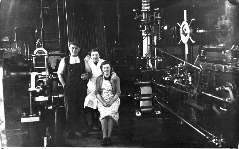
George Hogarth, engineer at Bancroft just after WW2 with the original Whitehead governor.
However, the original Bancroft governor was never a success. When the shed first started to weave the workers had to run out of the mill several times because the engine overspeeded, ‘ran boggart’ as we call it. This problem got worse after the Second World War when Bancroft ran a ‘moonlight’ or housewive’s shift. This entailed running the mill for four hours in the evening for weavers who couldn’t attend during the day. About 200 looms ran on this shift and the governor was set for 800 looms during the normal working day. The only way the Whitehead governor could have coped would have been to alter its adjustment every evening and in practice this was impractical and so the engineer had to govern the engine by altering the throttle valve. In 1948 Brown and Pickles removed the Whitehead and installed the present governor which cured the problem.
This governor that you are looking at is a Lumb governor made at Elland. These governors were widely recognised as being the best obtainable. I certainly had no problems with it and it kept the engine steady with a very small variation in speed.
Right, here we go! I’ll attempt a brief but comprehensive description of how it worked. The basic action of the governor is that as the speed rises the governor’s balls fly outwards and as the hinged linkage connecting the balls to the governor are deformed the thrust generated is absorbed by lifting the heavy bob weight in the centre. The characteristics of the governor are adjusted by balancing the weight of the balls against the bob weight so that at the designated governed speed of the engine the horizontal governor bars connected to the sleeve at the bottom of the bob weight are parallel with the floor.
These governor bars are captured in a fulcrum point mounted on a bracket which is part of the governor stand. As the governor bars are raised they force the left hand end of the bars down. The end of the bar is connected to a rod which transmits the motion via a series of bell cranks and rods round the back of the stand to the small arrangement of rods mounted in the sloping cast iron bracket on the front end of the casting which carries the turned governor column. All I want you to do at the moment is to recognise that the motion of the governor is being transmitted to these rods. They are connected to the linkage on the Dobson Block motion but we’ll describe this when we come on to a good picture of it.
Looking at the governor again, it is fairly clear I think how motion is developed in the governor and transmitted to the Dobson Block. However, we have a few complications that we have to look at. The reason why the Bancroft governor was so steady is that a fairly large movement on the governor only made a small alteration to the valve settings. This meant that the governor was very sensitive but steady, it ‘hunted’ very slowly and with minimum alteration to the valves.
We have to understand what this ‘hunting’ is. The governor is essentially a dynamic control system. By its very nature it cannot govern at rest, it can’t stop governing. The load changes by minute amounts constantly as looms are stopped and started in the mill and the governor is detecting these changes and is adjusting the valves to keep the engine speed constant. If load goes off the engine speeds up and the governor cuts steam admission back to slow the engine down, if load comes on it does the opposite. This constant variation is called hunting, the governor is hunting for the correct valve setting all the time.
If there is something wrong with the governor like bad design, stiff linkages, wear in the joints causing lost motion or bad maintenance and lubrication the governor doesn’t react quickly enough and by the time it applies a correction the condition has deteriorated and it has to make a big correction. This takes it beyond the point it was aiming at and it has to correct in the opposite direction. In real terms, the governor is swinging up and down wildly trying to achieve the correct speed but never gets there because it is reacting too slowly and too late. This is called hunting. Under these conditions the engine speed varies widely and the situation is unstable because if a major correction is called for the governor can’t cope and you either get a severe underspeed or the engine loses control and runs boggart. Many older type governors had a damper fitted on them, usually a piston working in an open ended cylinder full of oil. This smoothes the motion of the governor out but was an admission of defeat by the designer.
The Lumb governor at Bancroft had none of these faults. When running under normal conditions the governor bars appeared steady, the hunting movement was so small as to be undetectable to the eye.
We’ve already noted that one of the reasons why the governor was so accurate was because it was geared so that a considerable movement of the governor only made a small alteration to the valves. Putting it another way, the governor was only effective across a very narrow range of the total designed power output of the engine. When the engineer started the engine in the morning he set the governor by experience to the load he expected to have to provide for. The governor could cope with any variation in the load at this setting over a range of say 25hp. This adjustment was made by altering the length of the vertical rod which connected the left hand end of the governor bars to the linkage connected to the valves. During the day the load could quite easily vary by over 100hp so it looks as though the engineer is going to have to pay the penalty for having a sensitive governor, he is going to have to stand there all day altering the length of the governor rod.
Luckily for us, a man called Wilby recognised this need and devised an ingenious mechanism to deal with it. This is the compensator. Look closely in the bottom left hand corner of picture 18. You can just see the large nut and the opposing threads on the governor rod used to make the adjustment but your view of the nut is partially obscured by a small mechanism with a ratchet wheel in view at the front. There is a small handle on the front of it. If you turn this handle it rotates the nut on the governor rod by a system of gears. This is how you make your initial adjustment when starting.
The ratchet wheel you can see is keyed solid on to the shaft and rotates as the handle is turned. Conversely, if anything moves this ratchet wheel it rotates the shaft and adjusts the nut. There are actually two ratchet wheels mounted side by side with ratchet teeth machined in opposite directions. Just to the right of the ratchet wheels you will see what looks like a pair of callipers with the points almost touching the wheels. On the bar extending to the right from this ‘calliper’ you will see a link rod vanishing out of the picture. This rod is connected to the eccentric linkage to the valves and whilst the engine is running is constantly moving gently up and down oscillating the ‘callipers’. These callipers are actually the pawls which operate the ratchet wheels. One pawl acts to speed the engine up and the other acts to slow it down.
Now we come to the clever bit which is such a complicated motion that the only way to fully understand it is to watch it while it is working. When the engine is running at the correct speed and the governor is comfortably within its range the pawls are held away from the ratchet wheels. However, if the speed drops as load comes on the mechanism engages the appropriate pawl and winds the governor rod nut a fraction thus compensating for the extra load. If the speed rises it engages the other pawl and slows the engine down. It’s magic to watch this while the engine is running, the compensator will put on one tooth, have rest and then perhaps take one tooth off. This compensation mechanism operates all the time the engine is running.
There is more! About half way between the compensator and the end of the governor bar you will see a small wing nut. This adjusts the position of a pear shaped weight which rests on the compensator linkage and is in fact the mechanism which controls whether the compensator winds on or winds off. The alteration you can make with this wing nut is the most fundamental adjustment on the governor. Altering this nut alters the speed of the engine. It says much for the power of control exerted by the Wilby compensator that the smallest nut on the engine controls the largest force. Many engineers never touch this adjustment but I used it constantly.
I have already noted that by careful attention to valve settings, greasing the ropes, achieving constant steam pressure and attention to detail I was able to increase the speed of the engine without upsetting the weavers and thus raised production and wages in the mill. This small wing nut controlled all that. Proper adjustment of it had a tremendous effect on the profitability of the whole mill. I have also mentioned how small matters such as atmospheric pressure affected the running of the mill. Another key factor was temperature and humidity.
The major factor in variations caused by temperature and humidity was the effect they had on the efficiency of the friction drives in the mill, that is the ropes connecting the flywheel to the second motion pulley and the leather belts connecting the looms to the lineshafting. When humidity and temperature dropped the ropes and belts tightened and when they rose, the ropes and belts slackened. So in hot dry conditions the looms ran faster, in cold damp conditions the looms ran slower. There is an optimum speed for Lancashire looms which depends on loom condition, sorts of cloth and other factors. This is impossible to calculate but there is a way of allowing for it. We are talking here about a minute but crucially important adjustment.
I had a secret weapon called William Lambert, commonly known as ‘Billy Two Rivers’. He was a weaver on the pensioner’s side, under the lineshaft in the shed. He had been a tackler all his life but after injuring his neck carrying warps on his shoulder he went back to weaving. What that man didn’t know about Lancashire looms wasn’t worth knowing. When I had got the engine settled down after starting I used to take a stroll into the shed and stand under the lineshafting close to Billy’s looms. As far as the weavers were concerned it was just the engineer listening to his gearing but what I was actually doing was watching for a signal from Billy. He would make a small concealed gesture indicating more or less speed or leave it alone. The reason why we did this secretly was because weavers were a funny lot and if they had known what we were doing they would all have wanted a say.
I would go back in the engine house and make a tiny adjustment to the wing nut on the compensator and after about twenty minutes would go back in the shed again. Billy would give me the thumbs up. I often did the same after dinner as well. In this way I was adjusting the engine to the shed and it must have been an effective policy because productivity went up.
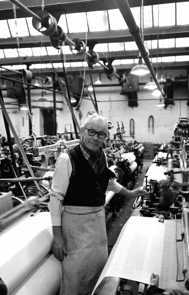
Billy Lambert, my secret agent!
I can almost hear the collective sigh of relief, at last he’s going to stop banging on about the governor. Hard luck kids, there is even more!
You have heard me talk about engines ‘running boggart’ and how dangerous this is. A steam engine has enormous reserve power and under certain conditions can start to accelerate and will not stop until it has reached a speed sufficient to burst the flywheel. Look at the insurance company records and you will find this was an ever-present danger. There are many reasons for this happening but they all have one thing in common, the governor has lost control of the engine. The designers of governors recognised this and we now have to look at the safety features incorporated in the design.
The threaded governor rod is the most important feature of these safety mechanisms. If this rod rises for any reason, steam admission is increased. A common cause of this was failure of the drive from the flywheel shaft to the governor. Under this circumstance the governor balls lose their power, the governor bars drop, the rod rises and the steam valves go to maximum admission. This is a recipe for disaster. The protection against this is the fact that the governor rod is made in two pieces connected by a hook. There is a small fixed point on the governor stand so arranged that when the engine is running, a small catch can be dropped which almost connects the fixed point to the lever which disengages the hook holding the governor rod together. This cannot be dropped in place until the engine has reached its normal running speed. Once in place, if the governor moves at all violently due to overspeed or sudden increased load or loss of drive to the mechanism, the catch contacts the lever on the hook, disconnects the two halves of the rod, the lower part of the governor rod falls and the Dobson Block motion stops operating the catches which open the steam valves. The effect of this is to instantly shut off the steam supply to the engine thus rendering it safe. Notice that the crucial factor in this safety mechanism is that the engineer has to remember to engage the safety catch once the engine is up to speed. If he forgets to do this, the engine is potentially dangerous. Almost all runaway engines are caused by failure to do this.
On a well set up engine with a steady governor the safety catch can be set to a very small clearance, That is, it is very sensitive to any unforeseen circumstance. The trick is to set it so it will accept the largest normal event, say setting one of the tape machines on, but react to anything greater than this. There is a penalty here which we have to consider. There was one common event which far exceeded the normal safety range of the mechanism. This was putting the shed lights on in dull weather. The engineer was responsible for deciding when the lights were put on and it was done by throwing a breaker on the main distribution board at the top end of the engine house on the HP side. This imposed an extra 100hp on the engine, far beyond what the safety gear could cope with. The way I dealt with that was to disengage the safety catch, wind the Wilby compensator open about five turns and then run round to the board and throw the breaker in. If the firebeater was handy I would get him to stand at the board and throw the breaker on my signal. Done properly the extra load could be imposed with hardly any variation in engine speed. Of course, I had to remember to re-engage the safety catch.
We are almost there now, just one more safety mechanism to note. You will notice that there is a shiny box mounted on the governor stand partially obscuring the governor rod and safety catch and connected by a flexible conduit to a pipe with a junction box. Quite obviously an electrical connection. This is the trip gear, an independent mechanism whereby a hammer is suspended above the lever that operates the hook that disconnects the two halves of the governor rod. This hammer is held up by an electro-magnet inside the box which is supplied with DC current through a circuit that runs right round the mill. At regular intervals along this circuit were what looked like fire alarm buttons but they were marked ‘EMERGENCY ENGINE STOP. BREAK GLASS’. If the glass was broken on one of these buttons it allowed the spring loaded switch inside to open, this broke the circuit, de-energised the electro-magnet, the hammer fell, the governor rod came apart and dropped and the steam was shut off to the engine. This system allowed anyone in the mill who was aware of a dangerous circumstance to stop the engine no matter where they were.
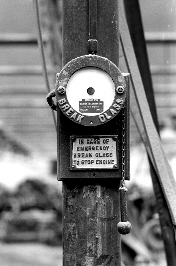
One of the engine stop buttons in the weaving shed.
I have a confession to make. I used to test this system occasionally at stopping time. Theoretically, if the system was working correctly, I could stop the engine by cutting off the supply of power to the circuit. It always worked perfectly, I cut the power and the hammer dropped. There was only one problem, it didn’t knock the catch out! I reported this and we played about with it but never got it to work reliably. In the end I ignored it because I could hear the hammer drop and so would have known that someone was trying to stop the engine. Reprehensible I know but this was real life and we had a living to make.
SCG/13 September 2003
10,038 words.
LANCASHIRE TEXTILE PROJECT
TAPE 78/AI/07 (Side two)
THIS TAPE HAS BEEN RECORDED ON APRIL 27TH 1979 AT 13 AVON DRIVE BARNOLDSWICK. THE INFORMANT IS STANLEY GRAHAM WHO WAS THE ENGINEER AT BANCROFT MILL AND WHO HAS BEEN THE INTERVIEWER ON MOST OF THE TAPES..
Bancroft folio, picture number 018. Negative number 776921
There’s very little left to describe in this picture. Hung on the wall on the right of the governor is the parallelogram gear which hung on the post we have seen on the bed and was connected to the crosshead. It was used when you were indicating the engine to convert the 4ft stroke of the engine into approximately 12” of movement on the string which drove the indicator’s chart drum. There were two sets of gear, one for each side of the engine and when not needed they were kept hung on the wall. The top of the column on the bed can be seen just to the left of the governor column.
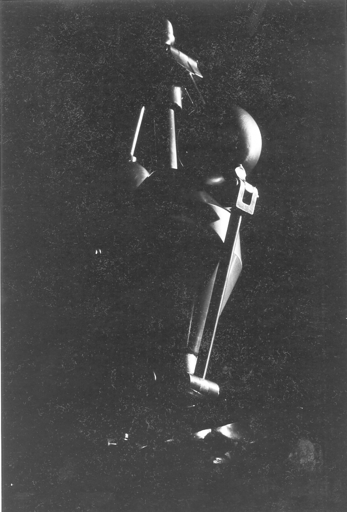
Picture number 019. Negative number 778807.
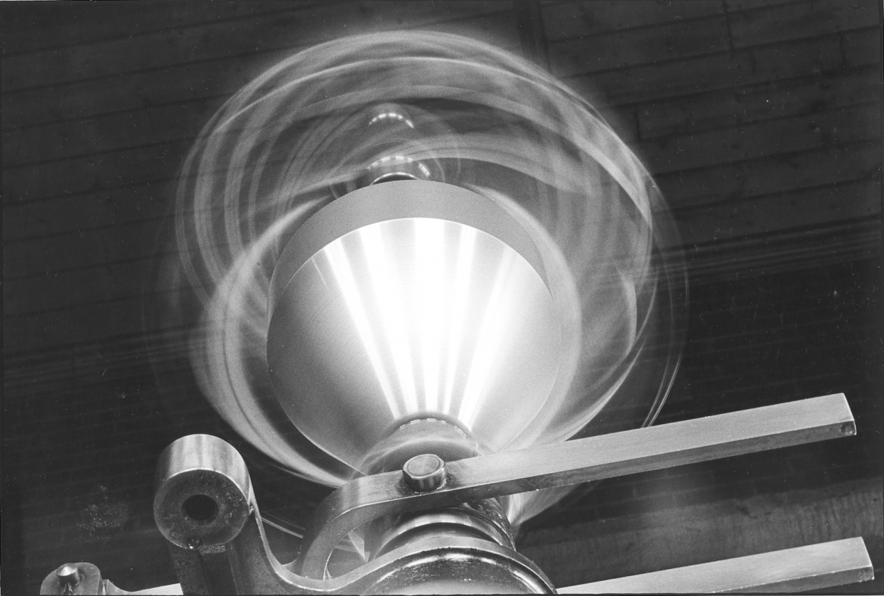
This picture simply gives an impression of the governor in motion. It clearly shows the groove in the bottom end of the bob weight which carried a bronze ring to which the governor bars were pinned. As the weight moved, so did the bars.
Picture number 020. Negative number 776139.
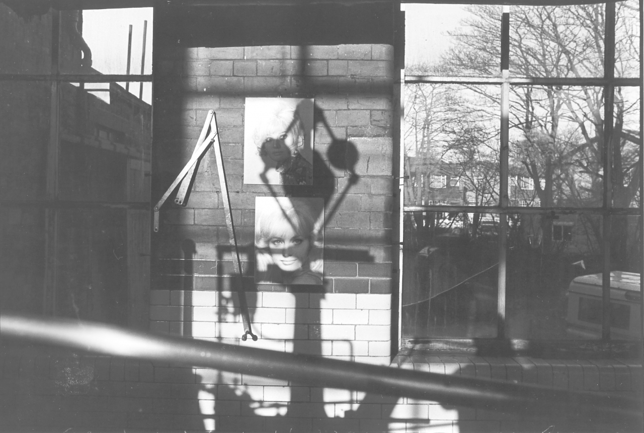
This is an indulgent picture, I was fascinated by the fact that though the governor was running it cast a stationary impression on the wall. Once again you can see the parallelogram gear on the wall and two pictures of a lady. These pictures were all over the engine house. They were the covers of the Shiloh calendars from previous years.
Picture number 021. Negative number 767602.
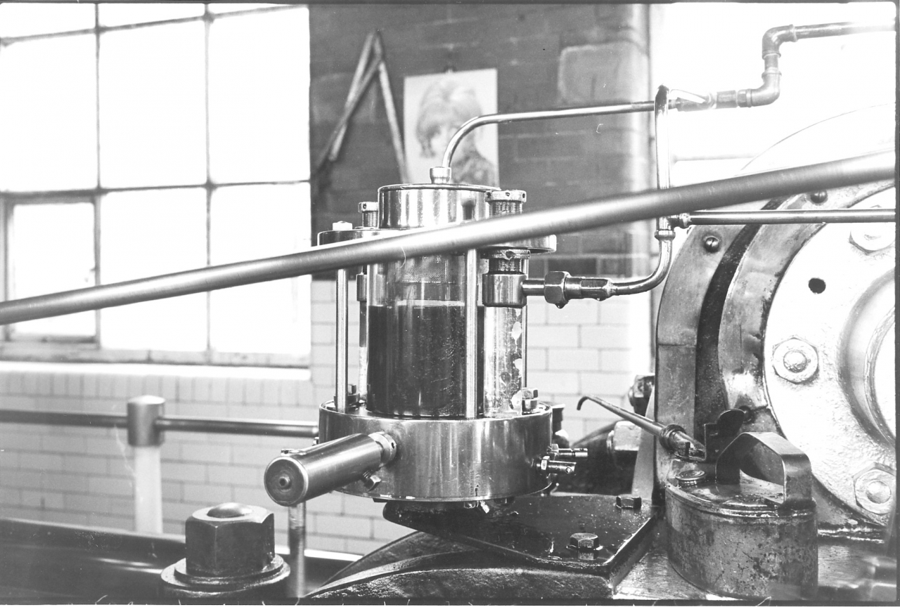
This is a picture of the high pressure cylinder lubricator. There is a story about this lubricator. The lubricator was made by J&W Kirkham Limited, Lark Street, Bolton. Their works was next to Musgrave’s steam engine works and they were the first firm to make a successful high pressure lubricator for steam engines and the Kirkham lubricator came to be the accepted standard against which others were judged. When I took the engine over I stripped this lubricator down and cleaned it out and judged that its performance could be improved by fitting new stainless steel ball seals and volute springs in the two pumps which are driven by the shaft passing into the base. This shaft by the way is driven by a linkage connected to the eccentric rods in such a way that the stroke can be varied.
I rang the company up and spoke to John Kirkham the owner. I complained about the performance of the lubricator and the non-availability of spares and he was quite taken aback because they stopped manufacturing this particular model in 1925/26! I think he must have taken to me because he sent me enough spares to keep the lubricator going for the next 25 years at no charge.
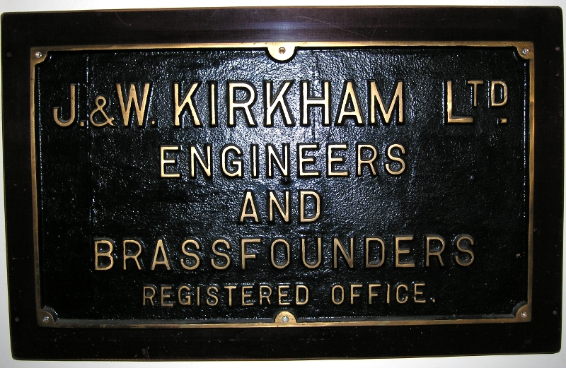
A replica of the brass name plate on the wall outside the works. There's a story behind this which illustrates some of the difficulties I came across in my carrer bringing redundant steam engines back to life. As soon as something becomes redundant it is targeted by thieves. I became a friend of John Kirkham and he helped me a lot when I was stuck with something on one of my engines. When they closed the works down he let me have a rummage in his pattern store and take what I wanted. I remember warning him that day about the nameplate next to the office door in the street. Sure enough, he rang me a day or two later to tell me it had been stolen. A few months later I presented him with a replica cast from the original pattern which I had 'rescued' from his pattern store. I had two more made, this one is on my wall at home and I gave the other to Ellenroad Trust.
The lubricator is specialised because it is pumping cylinder oil into the HP cylinder against boiler pressure. In other words the pumps and delivery glasses are working at over 140psi. The large glass tube in the centre is the reservoir and is made like this so that the oil level is always visible. The smaller glass tubes on each side are sight glasses through which the oil is delivered from the pumps. If you look closely you will see that there is a drop of oil in the middle of the left hand glass. The sight glass is full of distilled water and has a copper wire fixed in the centre. As oil is pumped in at the base of the tube it forms a droplet and when it has reached a sufficient size it breaks away and floats up through the water to the end of the delivery pipe at the top of the glass. In this way the flow of oil can be monitored very easily.
The next thing to recognise is where the oil is going to. When I took the engine over the two feeds went to a hole drilled in the steam chest above the middle of each steam valve. The theory was that it dripped on the valve and was distributed in the cylinder by the steam passing through the valve. As early as 1920 it was widely recognised that this was inefficient. I have a copy of a report made on the lubrication of the Bancroft engine in 1924 by the Vacuum Oil Company where they recommended another method. The best way to lubricate a steam engine was to introduce the oil into the steam main above the stop valve via a spoon shaped orifice with a slit in it. The effect of this was that the oil is atomised by the steam passing into the cylinder, [is entrained in the steam] and lubricates every internal part of the engine including the LP cylinder. I altered the oil feed by fitting an atomiser and cut down the amount of oil used by half and the engine ran a lot better. I did things like draw one of the low pressure valves out of its housing to examine it and the theory worked, the surfaces were lightly oiled. It had taken 49 years for the Vacuum Oil Company’s advice to be put into effect.
One of the HP steam valves, a light coating of oil.
A very important factor in cylinder lubrication is the formulation and quality of the cylinder oil. The first thing to be taken into account is the conditions inside the cylinder. There is a great deal of difference between a cylinder running on dry steam with high superheat as many later engines did and an engine like Bancroft running on what is known as ‘saturated steam’, in other words steam at boiler temperature which is carrying water with it. In the former case a very thick, high temperature oil is needed with characteristics which can resist the tendency to carbonise in the cylinder. For saturated steam you need an oil which can resist emulsification by the water in the steam. This isn’t rocket science and my way was to approach a firm called Walkers Century Oils at Newcastle under Lyme who I knew supplied all the cylinder oil to the National Coal Board for use in their steam winding engines. It was a fairly safe bet that they had investigated the properties of the oil supplied to them and ensured that it was correct. This was the case, I changed over to Walker’s oils and we saw an immediate drop in oil consumption and an improvement in the running of the engine.
As part of the process of deciding on which oil to use Walkers took a sample of the oil that we were using when I took over and reported that it wasn’t cylinder oil at all. I had seen the name ‘Core Oil’ on the barrels and had assumed that this was the name of the manufacturer. I was wrong, this was exactly what it was. It was an oil used in foundries to bind the cores used when casting metal into shapes with cavities in them. It was nothing to do with lubricating steam engines. The only properties that it had going for it were that it was cheap, black and thick. The Walker’s oil was thin and transparent. If you look at the drop travelling up the sight glass you can see that the light is shining through it. [In 1986 when I was running the Ellenroad engine I was in the fortunate position where I could call on the resources of the Total Oil Company to recommend the best oils to use on the Ellenroad Engine. By that date it was very difficult to find a supplier with technical experience of steam cylinder oil because the market had vanished. Total had not got an oil that would do the job. Walkers were still in business and Total approached them and got them to recommend a formulation. What we got eventually was an oil almost identical to the oil we had been using at Bancroft but with the addition of a modern ingredient that ensured that the residual oil left on the cylinder walls became a waxy coating when it cooled down, thus giving us increased protection during the long periods when the engine was stopped. As a matter of interest their recommendation for the thin oil used for lubricating the bearings on the engine was exactly what we had used at Bancroft. A straight SAE40 mineral oil.]
I will come back to an illustration of the quality of the cylinder oil when we describe one of the later pictures.
Also on picture 021 you can see one of the nuts on the holding down bolts at the front end of the cylinder casting. These were the only ones which were bolted dead tight. Even so, when the engine was heavily loaded if you looked very carefully at the joint between the cylinder casting and the base plate you could see a very slight movement as the engine was running.
The oil can resting on the casting to the right of the lubricator is an old one made of tinned steel plate. It holds cylinder oil and is kept on the casting so that it is hot. The handle could be grasped with the bare hand but the body of the can was hot enough to burn you.
If you look at the base of the lubricator on the right hand side you will see two threaded screws with lock nut securing them. The nearest screw is for adjusting the stroke of the internal pump and thence the amount of oil delivered at each stroke. The far screw is a stop screw. If it is screwed home on the seating at stops all oil delivery to the glass. This was used if a glass burst while the engine was running. There was a valve on the delivery pipe as well so that the glass could be isolated from the system while a new one was fitted. I have had sight glasses burst and have isolated the feed but never changed a glass while we were running. Because I had fitted new valves and springs in the pumps and because both pumps were delivering to the atomiser in the steam pipe all I had to do was increase the feed on the remaining pump.
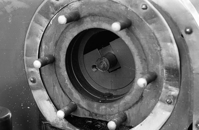
Picture number 022. Negative number 776213.
This is a closer view of the high pressure valve gear, showing clearly the Dobson Block, the valve rods and the back steam valve with the bell crank. Notice the small lubricators - this engine was running when I took this picture, that’s why it's slightly blurred. You can see the action of the catches from this photograph, the far one is open, it has let go of the valve rod and the spring loaded rod to the dashpot has slammed the valve shut. The near valve is closed and the catch on the Dobson Block has grabbed the valve rod and is opening it by pulling the back valve rod forward. This turns the bell crank, which rotates the valve spindle. This opens the valve and at the same time lifts up the dash-pot rod against the compression of the spring ready for snapping it shut when the catch on the Dobson Block leaves go of the end of the valve rod. This is a very simple motion and very efficient. It has its faults but it has tremendous advantages. There are no small springs, cams or catches to go wrong, everything very solidly built, and engineered to last a life time as was everything else on this engine. I should point out that when this engine was made redundant it was nowhere near worn out. The high pressure cylinder was bored or rather rebored and new valves fitted in about 1958. Brown and Pickles did the job and when Newton heard I was taking the cover off to fit a new packing he came up and measured it and the wear was negligible on it in 1976.
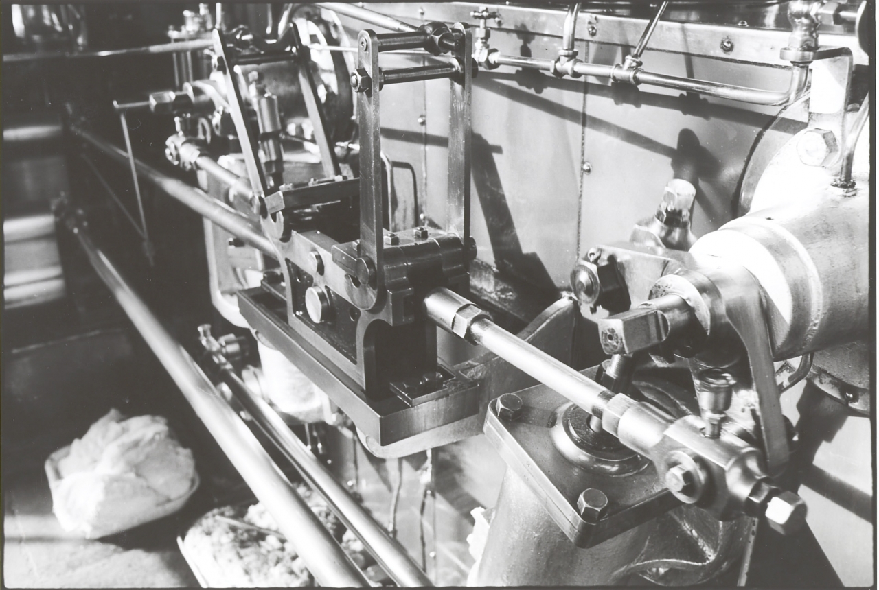
We have to descend into the mysteries of the governor again at this point. Notice the levers mounted on each end of the Dobson Block. Recognise two things about them. First, they are connected to the governor by the rods fitted to the top bar of the frame which holds the pair of levers rigid. Notice the hook on the base of each lever which contacts the catch plate mounted on the same pivot when the block has reached a certain position.
It’s important to realise that the rods from the governor do not move apart from the very small adjustments to the position of the end of the rod where it connects to the frame transmitted from the governor. In effect, this position of the top of the frame is a fixed point which can be adjusted by the governor. As the Dobson Block is driven backwards and forwards by the top eccentric rod the effect is to cause the levers attached to the governor rods to oscillate on their pivots. During this oscillation they alternately lift and drop the catch plates thus making or breaking the connection with the steam valves. The actual point in the block’s travel where they release the steam rod is adjusted by the governor moving the tops of the levers closer together or further apart. If they are moved towards each other the catch is released later in the piston travel. If they move the levers apart, the hooks lift the catch plate earlier. The linkage is so designed that if the governor rod drops the lever tops are moved so far apart that the catches are permanently held up thus stopping the ingress of steam to the cylinder. This simple mechanism can control the shutting position of the valve, the cut-off point, at any value from zero, always closed, to 90%, steam admission for 90% of the stroke.
One word about the catches themselves. The catch plate had a small dovetailed slot cut in each side into which a very precisely cut piece of leather could be inserted. This cushioned the contact of the catch plate with the block when it was dropped. These had to be very carefully fitted because they actually altered the grip the hardened steel wedge on the bottom of the catch plate had on the mating surface on the steam rod. The wedges themselves were made of high carbon steel treated after manufacture to make them ‘pot hard’, in other words, as hard as glass. This meant they were very brittle but this was no matter as they were solidly fixed to the catch plate by three countersunk headed bolts solidly nutted to the plate. Newton once told me that when making these wedges it was important to machine them so that any machining marks were in line with the motion of the catch. If this wasn’t done he said that the catches would give trouble in service. The wedges were machined in annealed condition and then heat treated to harden them after manufacture.
The wedges need to be hard because if you think about it, once they have been lifted to release them, the block drops them back down as it moves back in the opposite direction and in order to reach a position where it can operate again it has to ride backwards over its mating wedge and drop down again behind it. This constant contact and sliding motion over the mating wedge would wear the edge of the catch if it wasn’t dead hard. As far as I know, the wedges on the Bancroft engine are the original fittings.
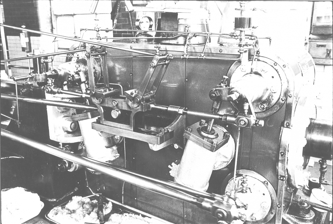
Picture number 023. Negative number 776217.
This is a general view of the inside face of the HP cylinder. The engine is running and the Dobson Block has almost reached the extremity of its forward travel. It will then reverse and open the front steam valve a fraction of a second before the piston reaches the end of its stroke. This admission slightly before the crank has reached dead centre is known as ‘lead’, the valve is ‘leading’ the piston. The affect of this is to ensure that when the piston reaches the end of its stroke steam is already entering the cylinder and cushions the end of the stroke. If you look very carefully at the front end of the back steam rod you can see the back edge of the hardened steel wedge which the catch plate will engage with as the Dobson Block reverses its stroke. Notice that all the rods have adjustment both for length and for adjusting the bronze bearings on the pivots.
This is a good view of the dashpots. Notice that the open end is covered by a heavy leather washer on the dashpot rod. This muffled the hollow noise that the piston made when it slammed down into the dashpot.
This view also shows the tin kettle specially shaped to sit inside the insulation to warm the cylinder oil up. You can see the handle just in front of the steam pipe framing the Shiloh lady’s face. Notice the handle of the drain cock in the tray. It is lying across the pipe, and not in line, this tells the engineer immediately that it is closed.
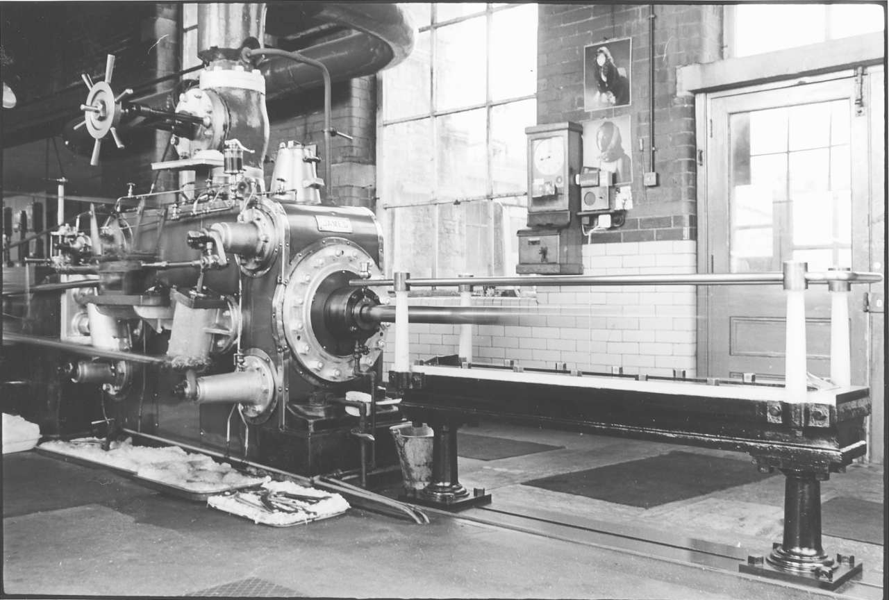
Picture number 024. Negative number 776204.
This is an overall view of the HP cylinder including the tail slide which, because of the long exposure has completely disappeared. This is a good place to discuss the question of tail rods. A lot of visitors used to ask why the engine had a tail rod on the HP side. They could see the reason for it on the LP as it was needed to drive the bell crank and thus power the air pump in the cellar. The HP tail rod looked redundant to them. In point of fact it probably was, plenty of cylinders of this size function quite reasonably without a tail rod. However, if you think about it. What we actually have here is a heavy steel rod probably 12 feet long with a heavy cast iron piston fitted on it. If there was no tail rod the piston would tend to lie in the bottom of the cylinder due to its weight not being supported. In practice this wasn’t necessarily the case while the engine was running. The inside of the cylinder is coated with a mixture of oil and condensate and the piston tends to float over this coating. However, it is undoubtedly a better quality of construction to support the back end of the rod and Roberts obviously made this decision when they designed the engine. Personally I like the idea, it is a more satisfying engineering solution. However, I have to admit that if there is no tail rod there is no need for a gland and no leakage because the cover is solid.
Think about the case if you had this piston rod set up on ‘V’ blocks outside the engine. You would have a heavy steel rod approximately twelve feet long with a heavy cast iron piston hung on it. The rod, despite its heavy construction, would sag slightly. Newton Pickles told me that when they were building these engines they would put the rod and piston on a lathe and jack it up in the middle to give it a slight curve or ‘set’ which compensated for the sag caused by the weight of the piston. There is a story about the Bancroft engine in this respect. Newton’s father, Johnny Pickles, once told him that when Bancroft engine was first installed the low pressure was giving a lot of trouble. He said that Roberts’ men stripped it down one weekend and rotated the piston and rod through 180 degrees. Johnny reckoned they had put a set in the rod but had assembled it the wrong way up. After that there was no trouble.
There is one more thing to consider about the fitting of a tail rod. Think back to our discussions about pistons and steam pressure. We have agreed that the force exerted on the piston is the product of steam pressure in pounds per square inch multiplied by the area of the piston. Take the example of a piston 16” in diameter. This gives a surface area of 201 square inches. Given a steam pressure of 140psi this gives a force on the piston of 28,140lbs. However, the area of the piston rendered unusable by the 3” diameter piston rod is 7 square inches, a loss of force of 980lbs. A loss of 3.5% of the effort. Consider a cylinder with no tail rod, the back end of the cylinder is producing 3.5% more effort than the front end and in order to get a smooth running engine this has to be allowed for in the valve setting. This is a relatively small amount but needs to be taken into consideration if you are aiming for perfection. However, a word of caution, there is a further complication to this matter which is to do with unequal events in the cylinder caused by the angularity of the connecting rod and the characteristics of driving on a crank. I don’t intend to go into this here, it is too complicated but if you are really interested, get a good book on steam engine principles and go further into it. And they say steam engines are simple machines….
At one time it was suspected there was a crack in the tail-rod of the Bancroft engine and while the new one was being made, the tail-rod was taken off, the gland blanked off with a piece of steel plate, and the engine was run without a tail-rod with no apparent ill effects.
At the back of the high pressure cylinder you'll see the other drain cock, coming out of the bottom of the cylinder, the back high pressure drain cock. There again, that's shut, the handle's in the cross position, if it was pushed down that was open. When you were starting the engine you always started with these drain cocks open in case there was a slug of water there. As the engine speeded up and the cylinder's got to working temperature and there was no chance of a slug being blown up the pipe the valves were shut so that you got full pressure otherwise you were wasting steam of course, it blew out down those pipes. You'll see that the drains from the steam bonnets to carry away condensation and oil into a pipe at the bottom of the cylinder and come down and then go down into the cellar. The bucket which stands at the back of the cylinder was the oily waste bucket. When you had dirtied a piece of waste and covered it with oil, you just threw it in there and when that bucket got full the firebeater used to take it down into the boiler house and throw it in with all the other dirty waste and it was used either for lighting the boiler fires or simply burnt at weekends in the firebox to give us a bit of steam and get rid of it.
Picture number 025. Negative number 777229.
This is just an overall picture of the high pressure side and the flywheel. The engine is stopped, notice that the governor bars are [down] on the stand and the spindle of the stop valve is as far in as it can go. You have clear view of the small ladder for oiling the governor and behind it the splash guard for the high pressure crank. Behind the governor is the distribution board for all the electricity in the mill and behind that the room where the alternator is. You can clearly see the pipe into which the bonnets drain into the cellar. Notice the drain cocks, it is immediately obvious they are open by the position of the handles. If you look at the gauges you can see the pig tail traps and the fact that the cock to the compound gauge is partly closed to stop vibration in the gauge. The cock on the steam gauge on the bottom right is choked down as well but that isn’t as obvious.
Picture number 026. Negative number 777236.
This is a picture of the back cover of the high pressure cylinder. The thistle oiler for the rod is clearly shown as is the large housing for the metallic packing. The most interesting thing about this picture is probably least obvious. Look at the pipe leading away from the drain valve at the bottom of the packing housing. Notice that it is covered in encrusted oil and carbon except for one part where the oil from the packing that escapes through the opening in the housing for the piston rod drips down on to the pipe and then into a small bowl underneath. I left this pipe like this to demonstrate what the effect of using good quality cylinder oil is. The whole of that pipe used to be covered with crust but as the new oil worked on it it gradually dissolved the old deposits away. I’m not suggesting that the internal surfaces in the engine were as heavily contaminated as this pipe but there is no doubt that some would be present. I think it’s fairly obvious why the engine ran better on the Walker’s oil. When the managing director asked me why our oil was more expensive I showed him this and told him to note the fact that we were using less. He went away and never queried it again.
The metallic packings were very good. There was never any leakage but occasionally you would see a thin drift of steam there especially if the light was behind it. This wasn’t leakage, it was simply a small amount of condensation carried out on the rod. As soon as it got to atmospheric pressure it flashed off into steam. This happened to a lot of the condensate in the engine that was exhausted into the receiver, it flashed into steam. Incidentally, one thing I could never understand was that the receiver pipe in the cellar wasn’t insulated. The engine would have been more efficient if it had been.
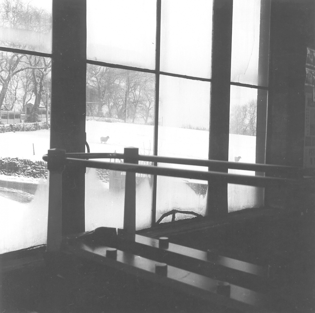
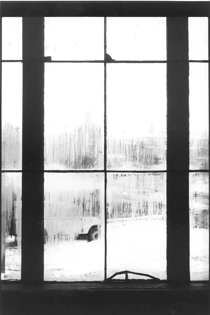
Pictures 027 and 028.
These illustrate the fact that there was a good view out of the engine house. The end window was made so that it could be removed in order to get the largest part of the engine out if need be. The condensation illustrates the fact that the atmosphere in the house was always moist. This was no problem as far as the engine was concerned because it was always warm.
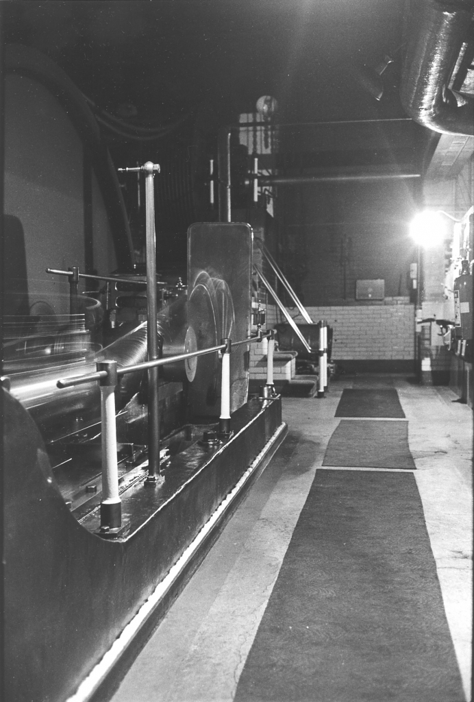
Picture number 029. Negative number 770203.
This is a picture down the high pressure side of the engine at night. This is a very long exposure, you can see that the con rod and crosshead have dissolved into streaks of light. I have to admit that I love making images like this, the engine actually looks alive. Notice the carpets on the floor. These helped deaden the echo in the house and modify the sound. They were also safer to walk on, less chance of slipping. Another advantage was that they tended to trap the dust that was always floating around. I always took the view that the more dust trapped in the carpet the less in the slides on the engine. One thing you may have noticed in the engine house is that I had no plants. The previous engineer used to grow tomatoes in there but I could never see the sense in it. What was the point in bringing grit into the house? I wanted to keep it out.
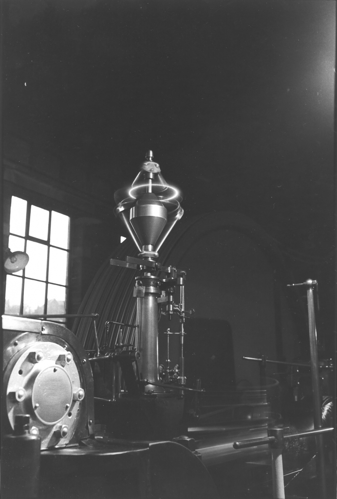
Picture number 030. Negative number 770241
This is a picture of the governor running on the edge of darkness illuminated by one point source of light. It used to fascinate me that this produced a halo.
One point of interest on this picture is that there is a small notice hung on the governor stand. Newton once told me that when they replaced the Whitehead governor in 1948 with the Lumb, the engineer was so pleased with it that he hung a notice on saying ‘The Boss’. When I had finished my improvements to the valve gear I was so pleased with the steadiness of the governor I put my own notice on; ‘I’m in charge’. It was too! It’s possible to get quite attached to an artefact that gives nothing but good service. One final point. If you look in the bottom left hand corner you can see the top of the front HP relief valve and the cover on the back of the front steam valve seating. Look at the casting in front of the cover. This is a rough casting straight from the foundry but notice that it is lightly oiled, shiny and the edges are polished by 60 years of wiping down. This finish can’t be reproduced artificially, it’s like the patina on a piece of furniture that has been cared for over the years. This gives an indication of the level of care and attention that was given to these lovely machines over the years. You don’t see electric motors polished like this.
SCG/13 September 2003
4,911 words.
LANCASHIRE TEXTILE PROJECT
TAPE 78/AI/08 (Side one)
THIS TAPE HAS BEEN RECORDED ON MAY 1ST 1979 AT 13 AVON DRIVE BARNOLDSWICK. THE INFORMANT IS STANLEY GRAHAM WHO WAS THE ENGINEER AT BANCROFT MILL AND WHO HAS BEEN THE INTERVIEWER ON MOST OF THE TAPES.
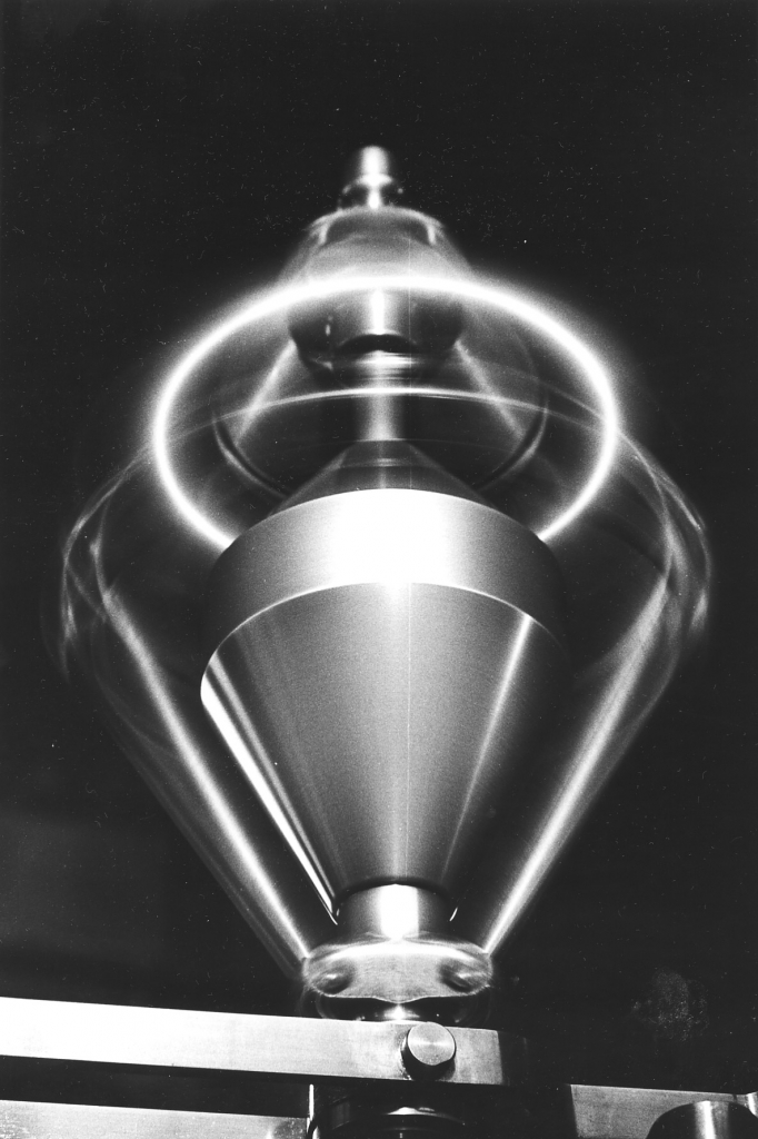
Bancroft folio, engine picture number 032. Negative number 770522.
We start today describing the pictures in the Bancroft Folio again with this picture of the governor at night. It’s taken on a very long exposure, with one point source of light, which means that you get some very interesting reflections from the metal parts of the governor. The halo at the top always amused me, the governor is a bit of a God, it looks after everything and it's almost saint-like. That halo of course is a reflection off the balls at the top of the governor which have faded out completely due to lack of exposure. The only thing that’s being recorded are the reflection of light. I must admit I've put it in because it was just a beautiful picture - but it does say a lot about the governor, it gives an impression of how precise the governor was, how precisely it was manufactured and what its function was. The links are thrown out by the speed, the links which hold the balls have been thrown out by the speed and the governor bar - that's the horizontal bar at the bottom- is horizontal, it's not drooping down, that governor is doing its job.
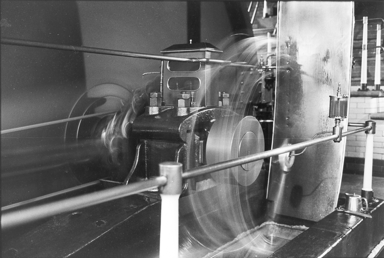
Picture number 033. Negative number 770516.
This is a picture of the high pressure crank pillow bearing and engine bed again done at night with a very long exposure. When I say at night I mean during the winter when we were running in the dark. This was one of the first films I shot in 1977 from the negative number and so it's going to be during January when of course it gets dark early at night. And what we are getting here is a picture of the engine which normally you couldn’t see with the human eye because even though the engine house was fairly well lit, there wasn't much light in this corner. The long exposure has done two things; it has brought into clarity the dark parts of the engine next to the flywheel which couldn't normally be seen, and it's got rid of the con rod and the crank, because of course they were moving so fast that they hadn’t time to register on the negative. The only thing which was registered are the point reflections of light from the single bulb up on the right hand side on the distributor board. A very interesting picture in many ways, it gives a lot of information. First of all you get a clear idea of the massive construction of the pillow block itself which contains the bearing which carries the flyshaft. If you look behind what looks to be the completely circular boss of the crank, but is of course just the part which was registered on the negative, if you look at nine o'clock on that circle on the flyshaft and crank and follow that into the pillow bearing you'll see a straight line which is the brass, it's the edge of one of the three brasses which actually form the bearing which carry the flyshaft in the pillow bearing. And, there seems to be a white mark down the inside of it, up against the pillow bearing. This is froth. It's a froth of oil caused by the fact that those bearings were moving slightly in the housing all the time. This isn't a faulty it's quite deliberate. You can't have bearings of this size and this nature nipped up until they are tight, you have got to allow some play. Remember that over the years this engine bed has settled and that flyshaft is no longer running dead true in those bearings, it couldn't be expected to, even on the best foundations there will be some alteration over the years.
Very clearly to be seen on the cap of the bearing, you can see the two big holding-down nuts and lock nuts at this side which hold the cap on to the bearing. These in fact on this bearing were tight because the cap didn't touch the shaft when it was nutted right down. Behind those holding-down nuts, the cap holding-down nuts, you can see a threaded rod stuck up with a square top and a lock-nut at the bottom. This was the method of actually adjusting the bearing. That threaded rod is threaded down through the cap and has a plain end at the bottom which bears on a cast iron wedge. The principle of adjustment is that you slacken the lock-nut off and turn the square top of that rod, that forces the threaded rod down which bears on the wedge and forces the wedge which lies between the body of the pillow block and the brass bearing further down in its housing. As it forces it down it pushes the bearing in, towards the shaft. So it’s obvious that the further down you force that wedge the nearer that bearing will be to the shaft, the less play there'll be in it and the tighter that bearing will be on the shaft.
People often ask exactly how we adjusted those bearings, because it's quite obvious, as I have said before, these bearings were of such a size that it wasn’t possible to nut them up tight and then shake the shaft or turn the shaft and see when they came slack. There was far too much weight involved. Here again, what you did was, when you thought one of those bearings needed adjusting, was to do it while the engine was running. The reason for this is that when the engine was stopped the weight of the shaft will be bearing on one of the brasses, usually the front one because of the weight of [the pull on] the ropes. As this is the one that carries most of the load it is the one that needs adjusting. If you try to drive the wedge down while the weight is on it you won’t get a result because you can’t expect a relatively small thread like this to move 30 odd tons of metal. So you do it while the engine is running and while the bearings are floating. You just give those a fraction of a turn, when I say a fraction, a sixteenth of a turn would be ample for one adjustment on that bearing. And of course you'd do both of them the same, and then you’d let it run, keeping a very careful eye on it. When I say keeping an eye on it, you keep a very careful hand on it. You go to it frequently and put your hand on the case of the pillow block and feel what the temperature is. The way you can tell when a bearing is adjusted to its limit is when you get it to the stage when the temperature is beginning to rise slightly. In point of fact you didn't look for that, what you did was just give it a fraction of a turn and then run it for two or three days or even more and see how it was and see if it cured the fault that you had observed in the first place.
The fault usually was that you could see the flyshaft moving slightly or you could see that the bearing was moving slightly when the thrust and counterthrust came on at that side. One general point should be made which applies to all the bearings on the engine. A sensible engineer leaves them alone unless there is a pressing reason for adjusting them. If you think about a comparison between these bearings and the relatively small bearings in say a car engine. Look at the tolerance advised by the automotive engineers and scale that amount of play up for the size of shaft and you will find that the large bearings have proportionately less play than the small ones.
On top of the bearing we have a good view of the aquarium lubricator. You can see two of the three oil taps inside which distribute the oil equally across the bearing. These dripped the oil down into funnels which contained a sieve, and from then on through plain holes right down through the cap so that the oil dropped on to the shaft. I should point out here that we never had one of these bearings out, but with big plain bearings like this at Bancroft there was no white metal in them, they were just bronze bearing. Note that we called them ‘brasses’ but this was a misnomer, they were never made of brass but of a special bronze which was alloyed to give good lubricating properties. The main ingredient was copper with small additions of tin and lead. It's essential that you have oil distribution galleries in the bearing. In other words you have got to let the oil into the bearing and once it's in you have got to distribute it across the face of the bearing. This was done by means of grooves cut on the inside of the bearing. One of the things to avoid with bearings like this is sharp edges because they tend to wipe the oil off instead of allowing it to stay on the shaft.
Perhaps the best way to illustrate this is to repeat a story that my father used to tell about an engine at Armstrong Whitworth’s, part of a group of engines, I think they were Willans high speed steam engines, which drove directly on to alternators and provided electric current for Armstrong Whitworth’s works in Manchester. They had a lot of trouble with one of them because the main bearings, the pillow bearings on the crankshaft kept heating up. It was decided to take this shaft out, re-face the journals, make new oversized bronze and white metal bearings and put them in to cure it. Unfortunately it didn't. In the end they found out that the reason why they hadn't cured it was that they'd made too good a job of the shaft. They turned it down until it was perfectly circular and then put a ground finish on it to make sure that it was absolutely the right size and perfectly true. Unfortunately they’d put such a good finish on the shaft that there was no room for the oil. The bearing wouldn't hold oil and it was in effect running dry. The important thing to realise about the lubrication of these bearings is that the oil is not fed in under pressure, it is a gravity feed. In order for this method to be efficient, there has to be enough room in the bearing not only for the oil to get in but to perform its function once it has got there. The technical term for the method of lubrication used at Bancroft and on most steam engine is ‘hydrodynamic’. This is full lubrication, the oil forms a barrier between the bronze bearing and the shaft so that they never touch. In order for this to occur there has to be enough room between the shaft and the bearing to allow a wedge of oil to build up in front of the shaft and as it tries to squeeze this out, it is channelled by grooves in the bearing surface which allow oil to be carried back under the shaft. It follows that this effect is helped if the shaft has sufficient grip on the oil film to carry it under itself. In addition, the edges of the bearing have to be chamfered so that the oil can get in to form the wedge and isn’t wiped off by the sharp edge. In the case of the Willans high speed engines at Armstrong Whitworth’s the cure was to file the shaft so as to destroy the too-perfect finish and allow pockets on the shaft to carry oil into the bearing. Remember that there are three elements to the bearings in this pillow block. One in the bottom and one at each side; the top is open and the oil is dropped on to the top bare side of the shaft. If there is a sharp edge on the bearing at the far side from where we are viewing it now, that will wipe that oil off instead of allowing to go in. And so it was essential that that bearing had quite a large chamfer cut on it and also oil galleries so that it would collect the oil and take it down into the bearing. Inside the bearing was another lateral gallery running right the way across but not actually coming out at the edge of the bearing, which allow a reservoir of oil to build up and be distributed equally across the face of the bearings on the inside. Very, very important the lubrication of these bearings.
The most common cause of temporary stoppage of steam engines was overheating of plain bearings. The usual cause was an oil stoppage or bad adjustment. I never had a ‘hot neck’ at Bancroft but in later years at Ellenroad had a small bearing heat up after an unknown ‘engineer’ decided to take the play out of it. It heated to the point where the bronze was melting in less than ten minutes and it was only a small bearing. There is an emergency cure for a bearing that has heated up. You allow the bearing to cool down and rectify whatever caused the overheating. What has happened inside the bearing is that the heat has melted the bronze and at the same time has destroyed the oil and allowed the shaft to rub on the bronze. The effect of this is to ‘rope’ the surface of the shaft. In a bad case this looks like corrugations. This is actually no detriment in a very slow moving bearing like a water wheel as long as the profile of the defects in the shaft matches the face of the bearing. A bearing like the Bancroft pillow bearing won’t be as bad as this but will be damaged.
The cure is to introduce a soft abrasive into the bearing and run it. By ‘soft abrasive’ I mean one which is not so hard that the metal of the shaft and the bearing can’t break it down. If it is too hard it embeds in the soft metal of the bearing and will simply stay there and accelerate wear. There was a proprietary powder called ‘Victory Compound’ and every engineer had some about him. This was mixed with oil, fed into the bearing and then washed out with a light spindle oil when it had done its job. The engine could usually be then re-started, run with plenty of oil flow and the oil in the aquarium changed a couple of times to get rid of any residue of the abrasive. Newton Pickles once told me that with water wheels they used to use a soft brick hammered until it was a fine powder. He reckoned that this was the main constituent of Victory Compound.
[It’s worth mentioning here another thing I have learned about bronze bearings by experience. The bronzes used for large bearings, and particularly in my experience the naval bronzes, are relatively plastic at normal temperatures. Over many years service they tend to deform in their housings and spread sideways, almost as though they were being squeezed out of the bearing housings. If you have overheating problems with an old bronze bearing, particularly one which could have been subjected to reciprocating shock loadings, like a cross head, crank pin or pillow bearing, look first to the fit of the shoulder of the bearing in the corner of the journal machined on the shaft or pin. Nine times out of ten this is where the problem will be, the shoulder will be bearing too tightly in the journal and no matter how much play there is in the face of the bearing it will build up heat in the shoulder, expand and run ‘stinking hot’.
At this point, an inexperienced fitter will dismantle the bearing and find unmistakeable signs of the bearing running too tight on the journal. He or she will also note damage on the shoulder of the brasses. They will not realise that the latter came first, expanded the metal and the former occurred as a consequence of the first. They will attack the fit on the face of the journal as the cause, ‘rectify’ that, put it back together and have exactly the same trouble. The cure is to remove a considerable amount off the shoulders. All bearings of this type are manufactured with an adequate amount of side float for this reason. I have never seen one get into trouble with having too much. Indeed, on many applications this side float is essential to good running to absorb movements in the running position of the journal due to other factors. The motion of steam locomotives has to have enough float to accommodate deflections in the running of the wheels due to curves and deformations of the track. Traction engine bearings mounted in the horn plates have to accommodate the same deformations due to running on uneven road surfaces. The flyshaft bearings on a large flywheel have to allow the non-perfectly balanced flywheel to float under the influence of unequal centrifugal forces.]
If you look at the flywheel itself, of course all the detail there has been blurred and all you can see are the circular parts, you'll see the big expanse of boarding itself. If you go in towards the centre of the shaft you'll see the circular marks caused by the actual boss, which was turned circular. Then before it reaches the centre you'll see that it appears that there is a black mark, a black circular mark, it looks like a gap, but of course one would think that there couldn't be a gap there because that flywheel had to be solid on that shaft. In point of fact it is a gap. It is surprising to a lot of modern engineers to see the method of fastening a large flywheel or pulley onto a shaft which was used in those days. The flyshaft is not circular where it goes through the flywheels or rather it has been turned circular, but it has had four (or more) big flats milled on to it. It is not a ‘plug’ fit in the centre of the flywheel, there is a clearance of perhaps, before the flats were machined in it, a clearance of at least an inch and probably more. The method of fixing the flywheel on to the shaft was by means of four very large, very precisely machined and fitted wedges, known as stakes. Two were put in from one side, and two were put in from the other; and by the degree and the order in which these stakes were driven up the flywheel was set perfectly true on the shaft. I have never seen this done but Newton Pickles tells me that you can do it with a board, a piece of chalk and two men and a big hammer. In actual fact with a flywheel this size they'd very nearly surely be tupped in. When I say tupped in, you'd have a chain hung on the block and at the bottom of the chain you have a large piece of metal suitable shaped on the end that’d probably weigh three or four hundredweight. You just swing it and let it hit the end of the wedge on the way back rather like the old fashioned battering ramp but slightly more scientific. That’d be used for the final tightening. [See Newton Pickles for a full description of staking a flywheel.]
Also in the centre can be seen two lines running away from the blur of the eccentric sheaves, one above and one below, back towards the governor. These are the governor ropes, three of them, cotton ropes, exactly the same as driving ropes but of course smaller which came off a pulley which sits in between the eccentric sheaves and the flywheel, mounted on the flyshaft. This drove the governor, so this meant that the speed, assuming that the ropes were gripping the pulleys, the speed of the governor varied directly with the speed of the flyshaft which of course gave the governing effect, gave the power for the governor to work.
If you look through the blur of the crank, above the flyshaft you'll see the cover of the slide valve on the nearest cylinder of the barring engine held on by ten nuts. On top of it you'll see the brass lubricator and that's about all the detail you can see of the barring engine itself. The action of the banjo-oiler is clearly seen here. The banjo is quite obviously in line with the centre shaft as its motion relative to the shaft is zero, it's just moving in a circular motion and the drip feed lubricator mounted on the rail is dripping oil directly into the banjo and it's being thrown out to the crankpin bearing from where it flies off and hits the splash tray behind. You can see the oil running down the splash tray, you can see that it's oiled up. On the engine bed near the stanchion in the right-hand corner you'll see a very thin piece of wire just beyond the oil kettle. That piece of wire was there for use if there was a blockage in the drip feed lubricator, usually a thread of cotton waste. You could screw the adjusting needle out of the lubricator and clear the blockage with the wire. Then there is the little tea pot which was solid brass. As I've said before this was a present to my mother and father and finished up being relegated to duties on the engine. It contained the reserve of oil for the drip feed lubricator. It was also used when starting or if the lubricator was blocked to pour oil straight into the banjo to lubricate the crank pin until the regular flow started from the drip feed oiler. Next there is a pair of gland nut pliers which were used to slacken off the adjustment on the lubricator if that needed altering. They very often did need altering because one of the faults of a drip feed lubricator is that as the temperature rises and the oil thins down they run a lot faster, it makes a big difference to them. Very often we used to start them off in the morning with the engine cold and we’d have to open them up a bit to get the right feed, the feed we wanted. As they warmed up we’d cut them back a bit. The lubricator has a sight glass at the bottom and I always used to reckon on about one drip every four revolutions for the high pressure side; if things were running exceptionally well five revolutions, if things weren't doing well perhaps a bit more, every three revolutions, or even two. The idea was to get a cushion of oil in the crankpin bearing because in common with all the other bearings, this bearing wasn't tight, it always had a slight amount of play in it. We used to have a saying that it was far better to hear them then smell them, in other words it was far better for a bearing to be slightly slack and knocking a bit than tight and overheating and burning the oil. You could smell the oil, of course that was serious, the engine had to be stopped straight away.
Notice the high polish on the rails. Everything that can be polished is polished and painted up, as I've said before we used to look after them. Tin tray in the bottom of the crankpit which catches the oil and returns it to the cellar. This is padded with waste round the sides to catch any excess oil and stop it going under the beds. In point of fact it was too late with this bed, oil had got underneath it and this bed was slightly loose. In the extreme bottom right-hand corner of the picture can be seen the trough on the side of the engine bed with the rope in it made of cotton waste to fulfil the same purpose on the outside.
Notice again the glazed bricks that we used for the first 5ft of the brickwork all the way around the engine house, very easy to keep clean, and a nice pleasing colour, they were cream and a very reddish brown at the bottom, all of them glazed up to about 5ft and from then on plain Accrington brick. [When I was working on Ellenroad engine I found out that these brown glazed bricks manufactured before WW1 Have to be treated with caution. The brown pigment used to colour them is an oxide of uranium and they are radio-active. They are not dangerous unless cut with an abrasive saw and the dust is inhaled.]
One further point about the flywheel boss which is not evident from the picture. The boss of the flywheel which carries the spokes and bears the stresses of being staked on to the shaft is made of cast iron. It was possible to get flywheel bosses cast with impure cast iron where patches of them were what we called ‘spongy’. They were full of tiny gas bubbles frozen into the casting as it cooled. If a keyway was cut through an area like this it could work loose and give trouble. In addition, cast iron is very weak in tension so the boss of the flywheel was strengthened by shrinking a forged steel ring on the periphery of the boss on each side in exactly the same way that a crank was shrunk on a shaft. This ensured that the boss could withstand the bursting pressure of the stakes being driven in to secure it on the shaft.
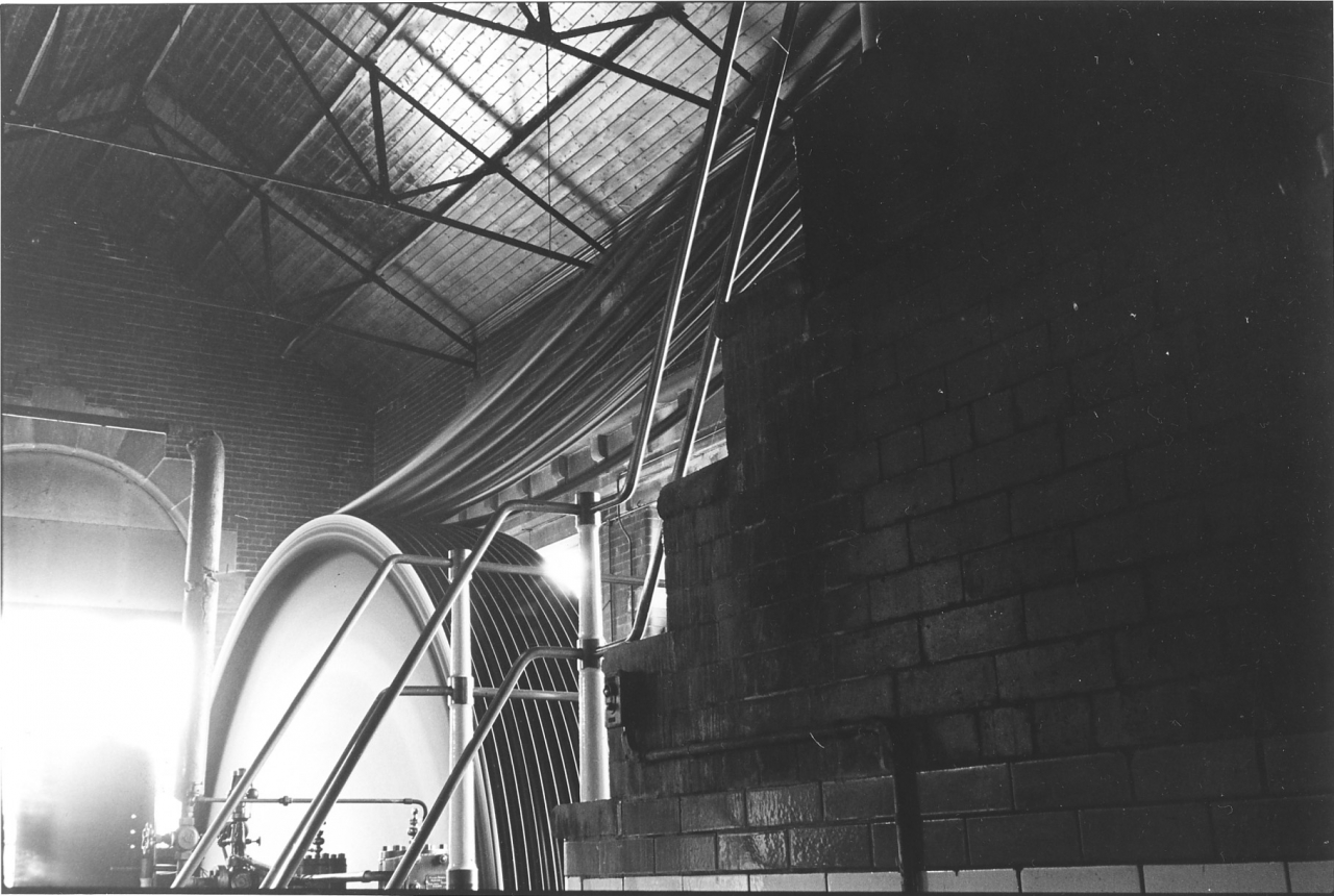
Picture number 034. Negative number 767642
This is a picture of the High Pressure side from the doorway in the top end of the house which led into the warehouse. One small point about this door. It was always bolted securely during the night and sometimes during the day as well. If I was doing anything that needed total concentration I would lock myself in so that I couldn’t be distracted by anyone. This sounds extreme but is necessary when you are dealing with something on the engine whilst it is running.
Notice the boarding in the engine house roof. This was to help stop condensation in the roof in winter. The construction of the roof is steel trusses, wooden purlins and joists with blue slate on the outside. The slates had evidently been clashed up on the underside with lime sand mortar because over the years it had deteriorated and if there was a strong wind a fine dust of sand and lime would fall on the engine. This was bad for the slides and I always kept an eye on it. The flywheel can be seen clearly with the ropes swinging away from the grooves in a smooth arc up to the second motion pulley. Notice that some ropes have more tension than others. This is a product of age, the quality of the ropes and the skill of the individual splicer who fitted them. Splicing large ropes like this is not an exact science. The amount they would stretch when in use was variable and the splicer had to use his experience to gauge how much initial tension to put on them.
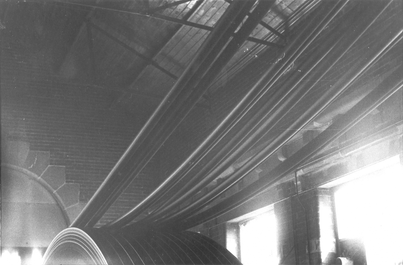
Picture number 035. Negative number 760636.
This is virtually a repeat of picture 34. Daniel Meadows and I competed with each other for the best rope picture and this was my favourite. It gives a very good impression of the movement and the power going up these ropes into the mill, its life force. Also evident are the large stone lintels over the side windows and the beautifully cut stones of the large arched window in the end of the house. The construction was brick on the inside but coursed rubble faced stone outside, all quarried on Tubber Hill.
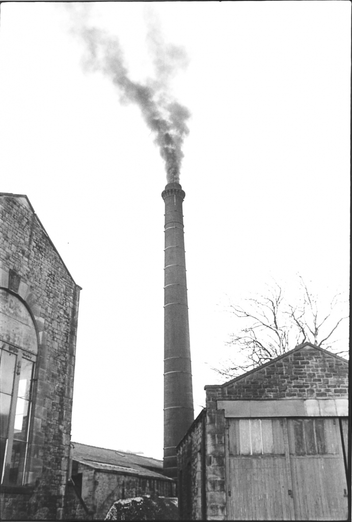

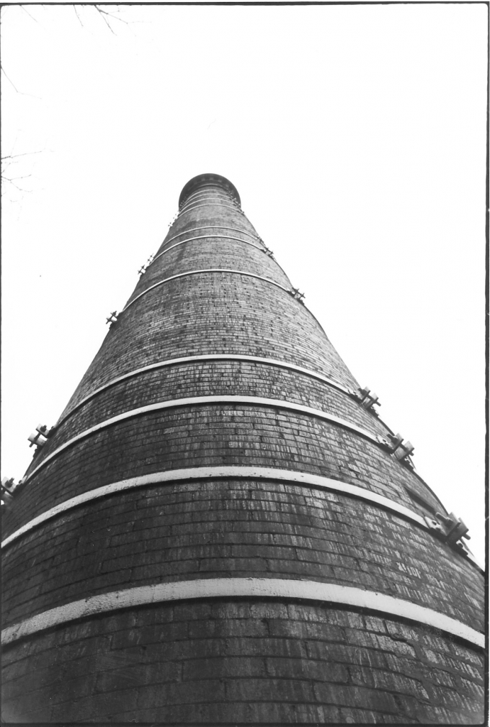
Picture number 036. Negative number 774022. Picture 037, negative number 772035. Picture 038, negative number 777514.
Picture 036. This picture shows the garage on the right which used to house the mill’s two motor wagons, the end of the engine house and of course the chimney. I have to confess that we shut the dampers for a couple of minutes while I did this picture so we got black smoke. Normally we never made smoke this dense but in the old days this volume of smoke would be common. The old engineers thought that you couldn’t make steam without smoke. A lot of them also had a superstition which had no foundation in fact, that a chimney drew better if a cast iron bar was laid across the top of it. Bancroft had such a bar on it and we removed it the first time I had it laddered. The origin of this is the fact that locomotive engineers knew that if an engine wasn’t drawing well due to a defective or badly designed blast pipe they could improve it by fitting a ‘jimmy’ which was a splitter on the blast pipe which increased the draught and made it easier to keep a working head of steam. It also increased coal consumption and was frowned on by the management. I believe that at some time an engineer at a mill heard about this practice, didn’t fully understand it but thought he would try it.
Picture 038. The chimney is 130 feet high and is built using special chimney bricks which are shaped to produce a circular structure. There are two types, ‘stretchers’ which have a curved shape longitudinally and ‘headers’ which are wedge shaped with a curved face and a convex face on the narrow end. There are iron bands on the chimney to strengthen it. I have never seen a picture of the chimney as built but do not think these bands are original. The story I have heard is that there was an earth tremor in the early fifties and the insurance companies insisted on many chimneys being banded as a precaution. These are wrought iron bands and are fitted by having turned up ends with holes in them and large bolts nipping them on to the chimney. There should always be a gap between these ends so that as corrosion builds behind the bands the tension generated in the band can dissipate by bending the turned up ends and not crushing the brickwork. If you know what you are looking for you can gauge the amount of corrosion behind the bands simply by looking at the angle of the bend on the ends of the bands. At the base of the chimney is the boiler house and if you look carefully you will see the end of the stockpile of coal we kept up the yard. We used to keep 200 tons in stock in case there was a transport or coal strike. The largest amount I have ever seen booked for stock at Bancroft was 700 tons or about 20 weeks supply in winter. The chimney was buttress construction. This means that there were two skins, an inner wall and an outer with internal buttresses for about the first 40 feet of the chimney. Above that it is solid. You can always tell a buttress chimney because they have air bricks in the lower part to allow air to circulate through the cavity. The first 30 feet of the chimney interior is lined with firebrick to protect the chimney from the hottest flue gas in the chimney base. You’ll notice some streaks perhaps on the exterior surface of the chimney. This is double boiled linseed oil which is painted on the outside of the stack to protect the bricks and pointing from the weather. This should be done every five years but Bancroft got no treatment whilst I was there, the firm ‘couldn’t afford it’.
Picture 039. Negative number 776732.
This picture was taken when the boiler was being blown down to empty it for annual maintenance in the summer holidays. Theoretically this is a very bad thing to do to a boiler but we had to get rid of the steam, open the boiler and flues up and let it cool down overnight sufficiently to allow the fluers to get in to do their job. We’ll talk more about the boiler later.
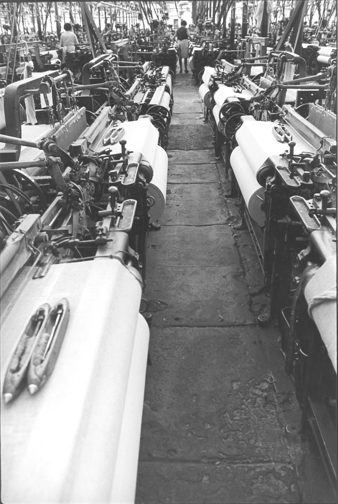
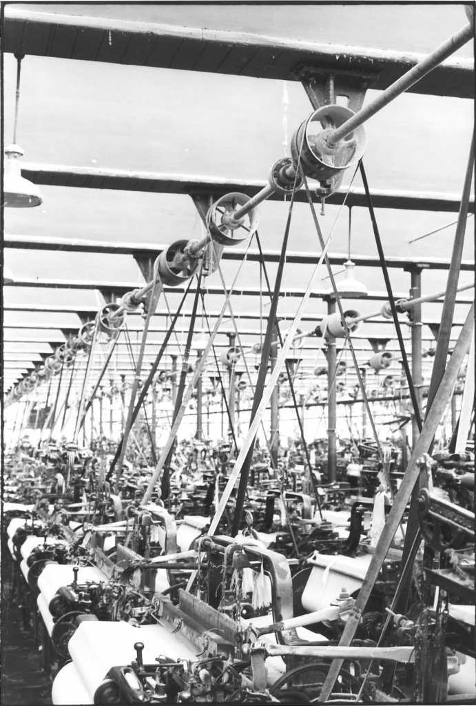
Pictures no 040 and 041. Negatives 789512 and 777520.
These are two pictures inside the weaving shed. The reason I've put these in at this point is to show where the power was going to. Very complicated pictures with a tremendous amount of information in them. On picture 41 you'll see the cross shaft which went across the mill, held in individual brackets on the pillars or the roof girders and running in brass bearings. This shaft was driven by a bevel gear on the lineshaft from the engine which was attached to the North wall of the shed. It carried the pulleys which drove the looms. Bancroft weaving shed was completely belt-driven, this is one of the things which made it such an amazing place in 1978. I don't know anywhere else where you could go into a [working] shed of that size, and see a power lay-out of this description still in its original condition. Absolutely typical of the later methods of building sheds. Cast iron pillars, girder construction, the girder is the gutter in between each valley of the north lights. We are not looking at the windows here, we are looking at the plaster on the reverse of the north light. In other words we are looking south. Bancroft Shed was a true north light shed. You'll find that this isn't always the case because many a time when they were building sheds, especially in towns where space was limited, they weren't always able to lay out the shed exactly as they wished. In the case of Bancroft they did it just exactly right. There are tie rods in between the girders gutters on the line of the pillars. These gutters weighed about 1cwt to the foot and together with the pillars were the most lucrative source of scrap when these sheds were demolished.
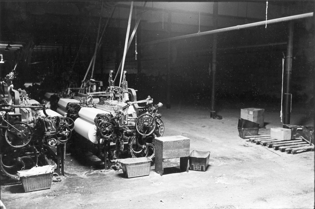
Picture 042. negative number 769119.
This is a picture of one of the looms at the back of the shed. I shall talk about looms later but this was put in to illustrate the fact that at night, when the engine was not running, there were only a few pilot lights in the shed to help you find your way round. In the depth of winter these were the conditions the weavers had to prepare their looms under before the engine started and the alternator powered the main lighting. In passing, notice the weft tins on the floor and the small buffet for the weaver to sit on if she had a moment to spare. You can also see the terrible state of the floor, but more of these things later.
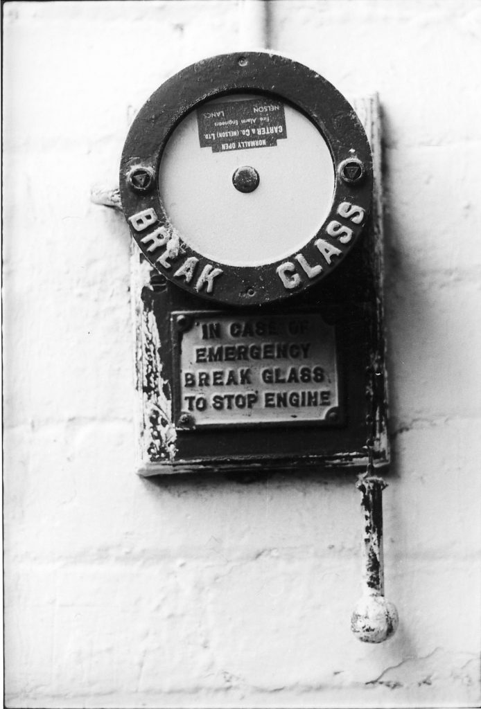
Picture number 043. Negative number 777630.
This is simply a picture of one of the engine stop buttons in the shed. Notice the small hammer hung down the side of it for breaking the glass. It was quite common for the glasses to be broken on the fire alarm buttons but I never had an engine stop glass broken. A good job actually as we only had a couple of spares.
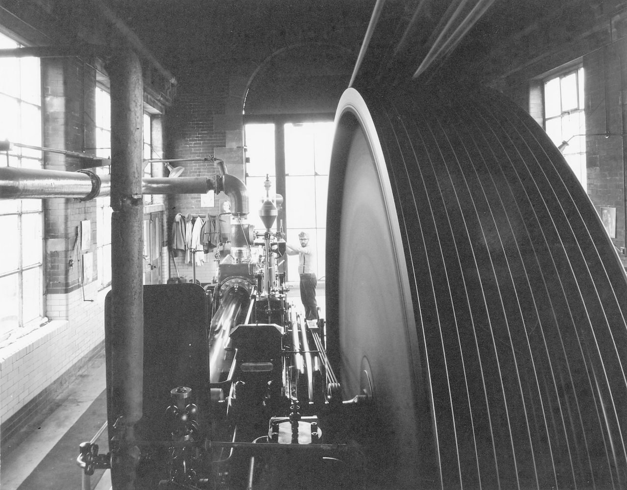
Picture number 44. No negative number. Pic by Charlie Meecham.
Picture number 44 is not one of my pictures obviously because I am on it. This is a picture done by a friend of mine called Charlie Meecham from Hebden Bridge, and is of exceptionally fine quality because it was done with a 5X4 plate camera. Really beautiful detail and probably the best way to take photographs in a place like an engine house, but the trouble is that it's very expensive, very slow and you don't get the number of shots done that you want to do to show all the detail. Very good detail down the high pressure side, you can see thy governor ropes clearly on the inside of the eccentric sheaves, you can see the eccentric rods running up towards the rocking blocks, the fish tank lubricator, the con rod, piston rod and cross head on the high pressure side blurred because of the exposure. I'm just stopping the engine I should say at that time. The reason I say that is because from the position of the balls on the governor the engine's running on speed and yet from the position of the spindle in the middle of the hand wheel of the stop valve which I'm turning, it's almost shut. It wouldn't be running at that speed if I was starting it. So I would say that I was just stopping that engine at dinner time. We can't see the clock, we can't see what the time is but I should say that I’m just stopping that engine at dinner time. It brings back a lot of happy memories that picture. I enjoyed myself running that engine.
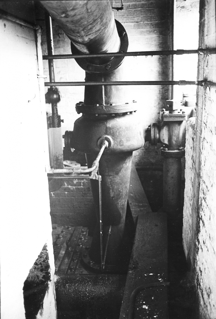
Picture number 045. Negative number 787309A
This is a picture in the cellar. On the left is the engine bed and in front of you is the jet condenser. Now this is the place where the vacuum was developed for the low pressure cylinder. The large pipe in the top of the picture going down into the top of the jet condenser is the exhaust pipe from the low pressure cylinder. On the right of the condenser can be seen a valve with a rod going up into the engine house. This is the inlet valve for the condenser water from the lodge and it was controlled by a lever up in the engine house. The vertical pipe under the valve leads directly to the foot valve and strainer in the lodge. The air pump [out of sight] on the left of the condenser, was sucking water out of the dam through that pipe, through the condenser, and thence out to run back to the dam as waste. As the water came in through the large valve on the right it entered a large annular ring on the conical body of the condenser at the top and from there was distributed as a spray into the condenser through a series of holes. This gave a very fine broken up spray of water inside the condenser which instantly condensed any hot steam coming in from the engine. All that was left to go out through the bottom was the condensate, the condenser water and entrained air which had come in with the steam and through leaks in the engine. This is the reason why these pumps were always called ‘air pumps’. In point of fact they were pumping water; because there was always leakage and you did get a lot of air entrained in the water that was going out of the condenser.
The smaller pipe coming out of the condenser low down is the connection to the vacuum gauge on the engine. The larger pipe above it which goes into the annular ring was a water supply from the mains which could be used under conditions of drought or very hot water in the dam to put cold water into the condenser. I did occasionally have to use that but in point of fact it wasn’t a great deal of use because if the water in the dam was low or hot, the water in the mains was usually at a fairly high temperature as well. And anyway it wasn’t really a big enough supply to make any appreciable difference.
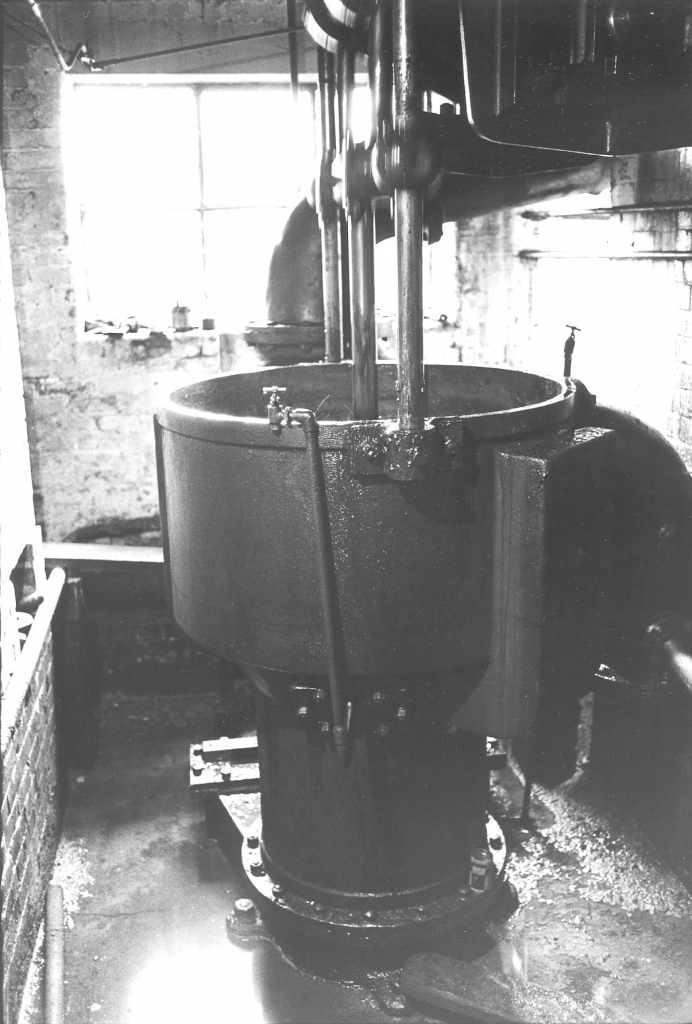
Picture number 046. Negative number 787228.
This is the air pump itself and is taken on the opposite side of the engine bed which was on the left in the previous picture. You can see the condenser behind the pump and the exhaust pipe from the LP cylinder. The linkage above is the bell crank which is driven off the low pressure tail slide. The two big brackets you can see hanging down, one at each side, carry the bearings on which the bell-crank is mounted and of course the far end of the bell crank is driving the rod up and down in the pump. The piston rod of the pump is the centre rod going into the pump. The two side rods are stay rods attached to the pump casting at the bottom and the engine bed casting at the top. The action was that the piston or more correctly, the bucket, was cast iron pierced with holes all over and on top of each of these holes was mounted a piece of rubber which acted as a clack valve. These were located and supported by cast iron saucers. These allowed water through the bucket on the down stroke but closed as the bucket moved upwards. This meant that when it was running the pump was always drawing water out of the condenser [via the coffin bottom] and hence applying a suction on the pipe from the dam as well. In the top of the main casting of the pump was a large cast iron plate with a gland in the middle through which the bucket rod passed. This ‘delivery plate’ was also pierced and fitted with rubber clack valve located and supported by saucers which allowed water to pass out of the body of the pump to overflow back to the dam when the bucket was rising. Both the condenser and the pump body were mounted on a hollow cast iron box called the ‘coffin bottom’, so called because it tapered at both ends and looked a bit like a coffin. Both the condenser and the pump were open at the bottom and so they connected with the coffin bottom. Between the condenser and the pump in the coffin bottom there was a cast iron grid covered on the pump side by a large rubber flap valve. This would allow the pump to pull water out of the condenser but would not allow any to be drawn back through by the vacuum in the condenser. There was also a non-return valve in the inlet pipe in the dam. The effect of these two valves was to ensure that when the engine was stopped the pipe from the dam maintained its water level and was always full.
Notice that there are two large square boxes on the side of the pump body casting. These were an idea of Roberts whereby they were going to form an air cushion and stop hammering in the pump which is always the big failure of air pumps. In point of fact it never worked and this was always a lousy air pump. You will notice two pipes with taps on top. These were snifting valves and the idea was that by bleeding air into the bottom of the pump using the vacuum in there, you could entrain more air in the water in the body of the pump and get even more cushioning of the large masses of water moving round in the pump body. These never did any good on this pump and we never had a good vacuum. Johnny Pickles recommended in 1935 that an Edwards air pump should be fitted but this was never done. It’s a shame because the Edwards is the best reciprocating air pump there is and would have given us a lot more vacuum and a lot less trouble. [It would also have saved thousands of tons of coal over the years. I'd estimate a ton of coal a week, over 60 years running this would amount to about 3,000 tons.]
SCG/18 September 2003
7,356 words.
LANCASHIRE TEXTILE PROJECT
TAPE 78/AI/08 (Side two)
THIS TAPE HAS BEEN RECORDED ON MAY 1ST 1979 AT 13 AVON DRIVE BARNOLDSWICK. THE INFORMANT IS STANLEY GRAHAM WHO WAS THE ENGINEER AT BANCROFT MILL AND WHO HAS BEEN THE INTERVIEWER ON MOST OF THE TAPES..
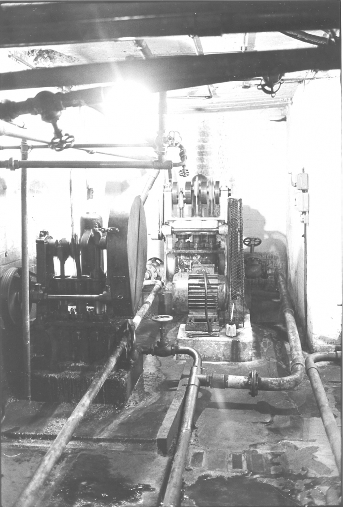
Bancroft folio, engine picture number 047. Negative number 787230.
This is a picture in the far end of the cellar of the boiler feed pumps. These are an essential part of any boiler installation. A boiler is, in effect, a large kettle boiling water and we all know what happens to the kettle at home if we let it keep on boiling, it eventually boils dry. The same thing happens in a large Lancashire boiler but the difference is that we can't take the lid off and pour water in, we have to force it in under pressure. I don't propose to talk a lot about this picture at the moment as regards describing its function in connection with the boiler, merely to point out the salient features of the picture itself because I shall talk more about feed pumps and feed water when we actually describe the boiler. One interesting thing about this picture is that if you notice, the cellar at Bancroft was whitewashed, it was whitewashed when the engine-was brand new. Jack Roberts, the last surviving member of the brothers who owned the firm of Roberts at Nelson says that when Bancroft was put in it was reckoned to be rather a superior installation because of the fact that it was stated on the contract that the boiler house, the engine house and the cellar had to be whitewashed. These pumps which you can see here aren't the original pumps that were fitted. Originally it used to be a steam injector and a Weir steam pump pumping water into the boiler through the connies. Over the years it was realized that this perhaps wasn't the best way of doing it and various installations were put in. When I came I altered it all again due to the fact that the pump on the left, which is a Pearn pump, made by Frank Pearn at Manchester, three throw electric pump, was in very bad condition and was not up to the job of keeping the boiler full of water. I put the pump in which stands at the far end, which is a Brown and Pickles pump. This was second hand when I bought it, obviously these pumps haven't been made for 30 or 40 years. This is a beautiful pump, far bigger than it needs to be but running very slowly. That pump would pump boiling water and that’s saying something for a reciprocating pump. It would take water that was almost on the verge of boiling and force it into that boiler. Which is what you need for boiler feed. The motor driving it, on the bed in front, the electric motor, is of more than passing interest. It's one of Horace Green’s from Cononley and it's a 10HP motor. Now this will look very large to people in the future who are looking at it, for a 10hp motor it looked very large in these days. Brook’s Motors of Huddersfield turned out a 10hp motor that was only about a third of the size of this one and a quarter of the weight but that motor of Horace Greens would deliver 10hp for ever. They were the Rolls Royce of electric motors and were made near Skipton at Cononley. They were just a fantastic motor, you never had any trouble with a Horace Green’s motor, full stop. They were built well within their job and they'd just carry on for ever. An amazing piece of machinery. If ever there's such a thing as an electric motor preservation society Horace Green’s motors ought to be the first ones that are put in. Newton once told me that Brown and Pickles’ had a 30hp Green’s motor driving the shafting in the machine shop at Wellhouse. During the war they had so much work on that the motor was being overloaded and started to stink. They sent for Horace Green and he came down and had a look at it. He told them it was all right, they could run it safely until the paint started to blister on the casing.
All the pipe work that you can see in the cellar there was done by myself and Bob Parkinson. We did it all ourselves and if you look very carefully, the pipe that comes down the right hand-side of the Brown & Pickles pump has a slight bend in it before it gets to the big bend which leads to the flange. This pipe had to be cut and welded again to make it fit in place. We did all this and used old second hand pipe. I think all that we'd bought was one piece of 3" pipe, everything else we robbed out of the original installation in the mill to repipe this engine house because the pipework was in shocking condition. Anyway, I'll talk more about that when I get on to talking about the boiler itself.
What we are going to do now is move on to a description of the pictures on taping. The reason why the numbering starts at 1 again is because these pictures were actually set out in the first place as separate folios when they were sent down to the Science Museum in London. With hindsight it would have been a lot better it we’d laid this folio out differently but you must bear with me and remember that we were working very much in the dark when I started doing this.
FOLIO OF TAPING PICTURES. Bancroft folio. Tape picture number 01. Negative number
This is a picture of Joe Nutter, a member of the original Nutter family who built the mill. He was taping at the age of 18. I'm going to talk very fully about Joe because he won't be talking about himself. He is still alive but he was very badly affected by the closing of the mill. When I say badly affected, I don't mean that his health suffered or his mental health suffered but we found as the mill was running down it rather caught us unaware. I didn't really expect the mill to close down so quickly and so thought that we'd get all the descriptions by the individual workers done before we finished. In point of fact that didn't happen, the mill closed down first. I’m afraid that it so affected Joe that he just didn't want to talk about his job or the mill or the Nutters. It was a disappointment for me but I quite understand it. I will admit that I was rather annoyed at the time but I can quite understand it, he was just absolutely sick and didn't want to talk about it. So what I've done, I shall describe these pictures and I have found another gentleman who was a taper all his life, very similar sort of a career to Joe and I shall record him describing Joe's pictures. This won't be exactly the same as Joe describing them, but is the best that I can do under the circumstances. So I shall go through these pictures quite quickly and give my description of what was happening. {The man I found was of course Horace Thornton and there is a full description of the taping pictures by him. However, seeing them from the engineer's point of view might bring out different aspects of the job. Remamber also that at the time I did this I didn't know how good Horace would be.]
[Anyone who has looked at all the transcripts will realise that I recorded my taper in July 1979. Horace Thornton of Earby proved to be a wonderful informant and I acquired a lot of information that Joe Nutter couldn’t have given me. See the 79/AD series of transcripts.]
SG description of the taping pictures.
I should say first what taping is. Taping, warp-sizing, or slashing, is the process of taking in back beams with the requisite number of threads in the set and making up weavers' beams fit to go into the loom after they have their healds and reeds put on them. This involves a certain number of things; one is making sure that there is the correct number of ends and count of yarn on each beam. The other essential part of taping is making sure that that [weaver's] beam has been sized correctly. Now, the reason for sizing a weavers’ warp, which is impregnating the individual threads with a mixture of starch and tallow and various other ingredients and then drying it, is to give the yarn elasticity which makes it better able to withstand the shocks of weaving in the loom and probably more important, to stop it penning up. Now penning up is the process whereby dawn gradually comes off the outside of the fibre and builds up in the reeds and healds to the extent where it blocks the gap that the thread's running through and breaks the end causing breakages. This is a very serious fault, and makes for very bad weaving. This is one of sizing's main jobs, to stop that happening.
In the old days sizing used to have an additional function. In the days when cloth was sold by weight it used to be an advantage to put as much weight into the cloth as possible, in the form of size. This was done by very heavy additions of china clay to the size mixture and this was known as the period of heavy sizing. It was very bad, not only from the point of view that it was dishonest but from the fact that it greatly increased the dust in the shed by reason of the china clay coming off the yarn. This made conditions as regards health in sheds, especially damp sheds, very bad for the weavers. This was the main cause of things like weaver’s cough, Bissinosis and similar industrial diseases. The heavy additions of size increased the amount of dust in the air.
So that's briefly what sizing is and that's what we are going to describe.
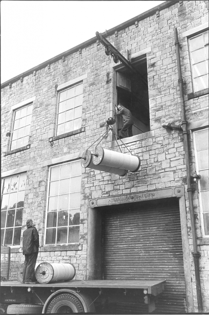
Picture number 2. Negative number 7718523.
This is a picture of the front of the mill and shows Jim Pollard the shed manager taking in a set of beams from one of Jackson’s wagons outside. These beams came from the spinners who made them up, and I'm just looking to see if I can see the name on these. I can’t see the name on them actually, they look like beams from Manor Mill but I can't see the name on them. These beams came to us in sets, more about that later, I’ll describe the set when we get to it. On this picture Jim’s lifting them up and taking them into the top floor by way of the teagle hoist. Actually it was a Baldwin hoist, it was made by Baldwins of Burnley, but they always got called the teagle or the cathead. The hoist could lift half a ton, it was tested to half a ton. An interesting thing to notice is the heavy cast iron surround round the loading bay, round the roller shutters to stop damage and of course they had cast iron at the top acting as the lintel and beautiful dressed stone construction of the mill, random dressed. This mill was beautifully built and no reason why it shouldn't have stood up for a lot longer.
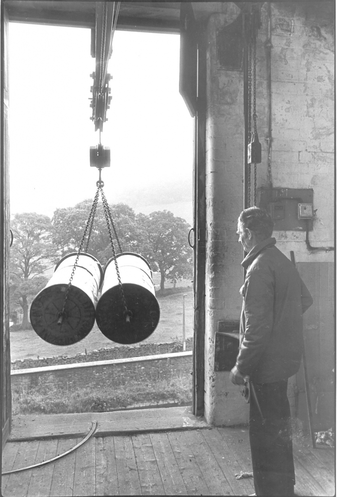
Picture number 3. Negative number 7718528.
This is a picture on the top floor showing Jim bringing the beams that you've seen going up, bringing them into the top floor of the warehouse. The preparation floor.
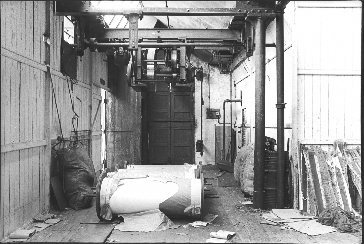
Picture number 4. Negative number 7718016.
This is a picture of the bay where the teagle is with the door shut at the end. The teagle mechanism can be seen up in the rafters, it was driven by an electric motor. Originally it was driven by the engine shafting and you could only use it when the engine was running. If you got a delivery when the engine was stopped they used to roll the beams into the cart-race at the bottom and then when the engine started, the next time it started, roll them out into the yard and lift them up then. So it was really a slight disadvantage but no great problem. One interesting thing about this place is that when we are looking at the pictures of the tape room which is to the left on this picture, notice that there are no cast iron pillars, the tape room is built with no cast iron pillars. The thing that's holding the roof up is a series of Warren trusses and these are carried on the cast iron pillar to the right which in common with the pillar in the warehouse below is a heavier pillar than normal because it's carrying all the weight of the tape room roof. The Warren trusses go right the way across the top of the tape room to the left and support all the weight of the roof. There is a clear space underneath for the tapes.
On the floor can be seen the set of beams which has just come in which evidently consists of four beams. Now, a quick word about the method of getting the right number of threads on each warp. The method was, if the weavers warps needed say 3000 threads on each, the set of back beams which was ordered to make up those weavers warps would in total have 3,000 ends on it. In other words it might be six beams of 20,000 yards each, in other words 20,000 yards of thread on each beam of 500 ends. So that when those six beams were put through the machine together, it came out at the other end as 3,000 ends and they were put on weavers beams, probably l,000 yards on each weaver’s beam. So a 20,000 yards set would make 20 weavers beams. And obviously, if the number was different, it would split up differently. These four beams would probably be for something quite light. It could be anything up to 700 or 750 ends on these beams but more usually 3 to 500 ends. So this was probably for a fairly light sort. Looking at it, quite possibly something like 2,000 ends in a weaver’s beam, 500 ends on each back beam because those beams aren’t full right to the top which makes me think that that was very fine yarn that was on there. Or quite fine yarn for Bancroft. That'd mean that they'd probably be about 25,000 yard beams but fairly fine stuff. If it was fine count, we didn't do any really strong cloth or we did very little really strong cloth in fine yarns so it wouldn’t be a very heavy count in the warp. In other words it'd probably be no more than about 2,000 ends in the weaver’s beam which would make fairly light cloth.
Old healds on the floor there, on the right hand side. Healds and reeds that have come off warps in the shed waiting to be put back on a weaver’s beam or waiting to be scrapped. More about those later when we get on about preparation.
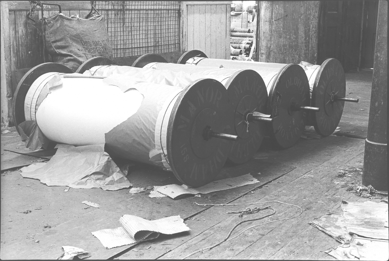
Picture number 5. Negative number 7718212A.
This is a close up picture of those four back beams which came in that day, and there they are, from Manor, at Oldham. Four back beams ready to go into the tape room and be put on the tape machine. Notice the cardboard on the floor under the beams. If beams were full to the top they could pick splinters up from the floor or have threads damaged by the rough boards. This cardboard was a cheap and cheerful way of guarding against this.
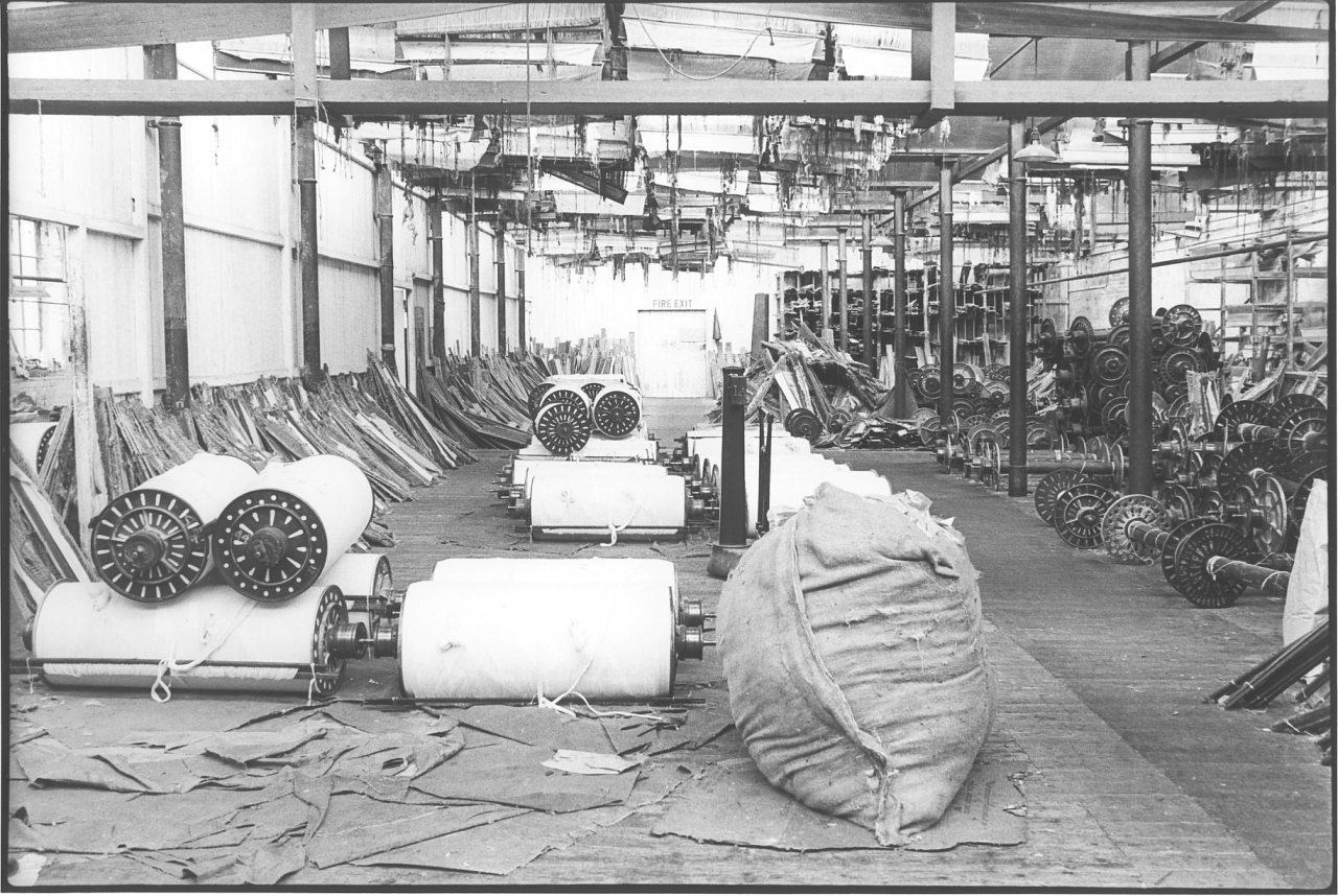
Picture number 6. Negative number 7718013.
This is an overall view of the storage area in the preparation department upstairs. We are standing with our back to the tape room, in very much the same position from where the two photographs were taken of the set of back beams. We are looking down towards the winders department which is through the door marked 'Fire Exit'. On the left is a wooden partition which divides the twisting room from the rest of the floor and outside here was used for storage of things like beams, healds, reeds, warps ready for going into the twisting room, and cotton waste. Anything that needed storing or keeping about. All very flammable stuff needless to say, and the fire insurance was very heavy. The building was completely protected by a sprinkler system. This is the same construction as the rest of the mill if you notice, north light roof on top of the preparation department, cast iron pillars. This is of course the second floor and those pillars are duplicated below the floor, down to the concrete floor of the warehouse. All this space is empty now and is just one tremendously big floor. All the partitions have been taken out, the machinery and everything else as part of the demolition of the mill.
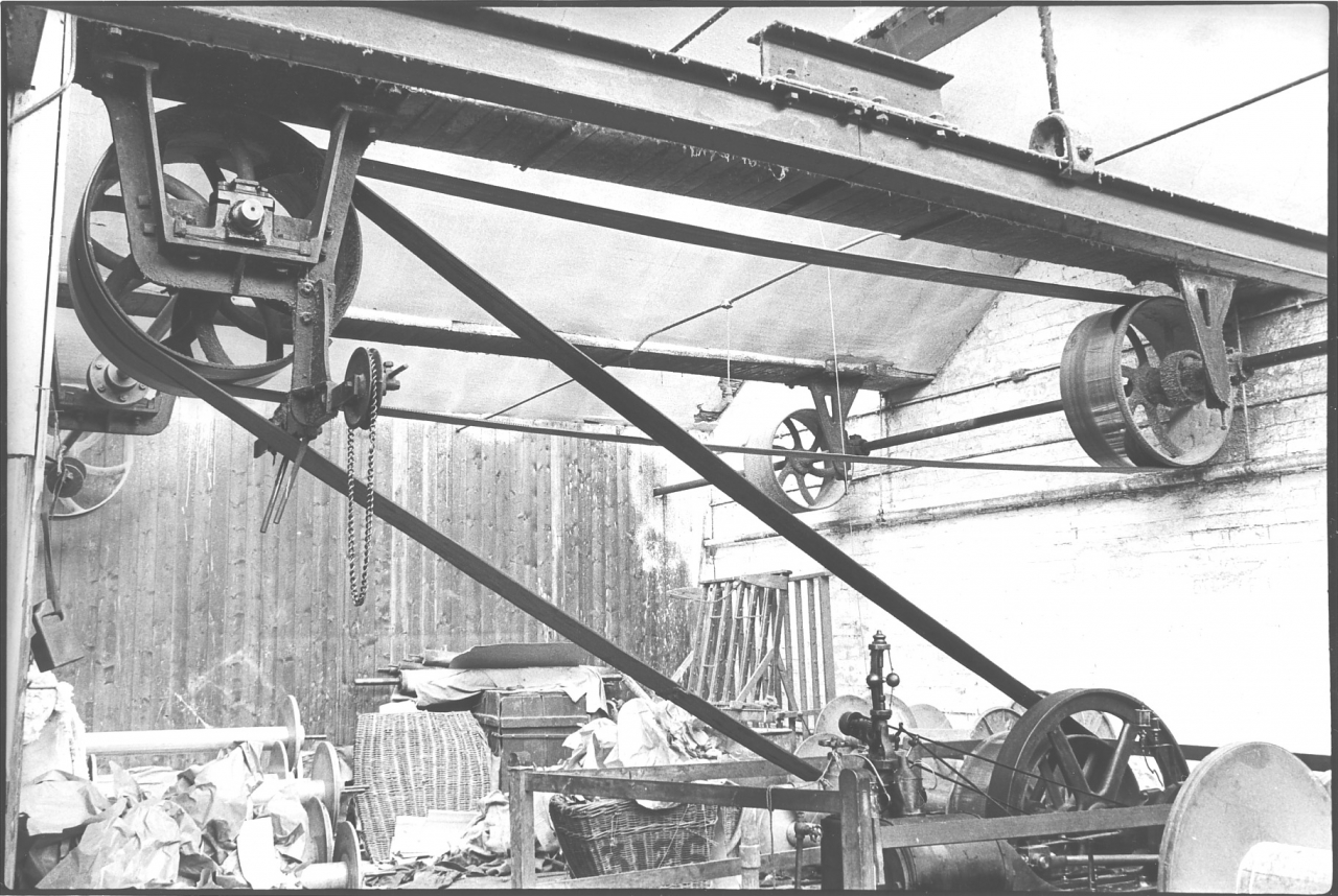
Picture number 7. Negative number 7718236A.
This is a picture of the corner of the tape room just behind the door as you go into it from where we were stood taking the pictures of the beams. It is a picture mainly of the arrangement of the belt drive to the tapes. You'll see that we have a shaft coming along the back wall of the room with a couple of large pulleys on it. That shaft originally went straight down that wall and drove the winders as well, but those have long since been converted to electricity so it didn't go any further than just beyond that partition. That shaft is driven off the engine by a four rope drive coming up out of the warehouse, we will see it in a later picture in the back corner of the tape room. Whenever the engine turns, that shaft turns. The belt driven by the pulley on the back wall runs across to the middle of the three pulleys on the left hand-side. The middle pulley of that group of three is the only one that is fast on the shaft running away down through the partition. The two outside pulleys are loose on the shaft, these are what are known as fast and loose pulleys.
In the position that it is in on this picture the engine shaft is driving the belt across on to the middle pulley of that shaft which is fast on to the shaft and which is driving that shaft which drives the pulley at the far end. That in turn drives another belt which goes across to the front side of the building and drives the pulley on another shaft which takes the drive into the tapes themselves. This seemingly complicated arrangement was necessary due to the fact that there used to be three tapes in this room and there was no room in the middle of the room to take the drive across because the roof space was already cluttered up with drives for fans and the tapes. So it was taken in at the far side. It’s also complicated by the fact that if you look on the floor there and also on
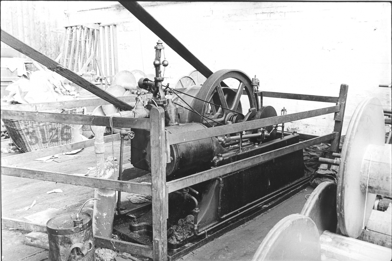
Picture number 8. Negative number 7718232A.
You will see the donkey engine which is another steam engine. The reason for this engine is that taping is a continual process, you don’t want to have to stop. You need to be able to start and run right the way through a set which leads to more even warps and the minimum of spoiled yarn. So the tapers kept working during the dinner hour. The engine stops at the dinner hour and the tapes have to keep going so just before dinner the donkey engine was started and as the main engine stopped the drive was taken over by the donkey. If you look on picture 7 you’ll see a chain hung down off a pulley. This operated a fork through which the belt ran and this moved the engine belt over to the far loose pulley and at the same time moved the donkey engine belt over on to the fast pulley. So when the main engine stopped the tapes carried on running powered by the donkey engine.
This donkey engine is a very interesting little engine because it is actually the last Brown & Pickles engine left running. Luckily it has not been scrapped but has been bought by a gentleman called Robert Aram and now lives down in Nottinghamshire. These engines were built by Brown and Pickles in considerable numbers and used for fitting mills up. It was very often cheaper for a large engine maker to buy a small engine like this off an independent maker like Brown and Pickles rather than make one themselves. The donkey engine wasn't running there because the governor is at rest. This was another Pickering type governor or rather an English copy of the Pickering the same as the one on the barring engine. There are two drain cocks piped into the bottom of the cylinder and a simple banjo lubricator feeding the crank pin on the disc crank. The main bearing is fed by another drip feed lubricator. Donkey engines were peculiarly liable to wear by virtue of the fact that they were looked after by the tapers and not by the engineer. And unfortunately the need for lubrication and correct tightening of glands and things like that weren't always fully realised and donkey engines did wear faster than the other engine down in the main engine house. The feed of steam to that donkey engine was 80psi as was all the steam up to the tapes. It was reduced from boiler pressure by a pressure reduction valve in the separate steam main where it left the boiler. This arrangement of a separate feed to the tapes was a product of the fact that if the mill was really busy the tapes might have to do overtime. Having a separate main meant that if necessary the steam main to the engine could be cut off at the junction valve on the boiler but the tapes could still function. Another advantage was that by operating at a lower pressure through the reduction valve the tapers knew they were getting the same pressure all the time. They were not affected by variations in boiler pressure.
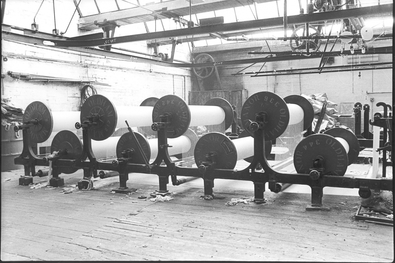
Picture number 9. Negative number 7718214A.
This is an overall picture of the creel at the back of the tape which carries the set of back beams which are being used to make the weaver’s warps. As you can see this is a fairly big set. There are eight back beams in that set. The individual threads of each one are lead down under rollers at the bottom and all of them come forward in a continuous web at the front where they actually go into the tape. Other interesting things about that picture to notice are the north light construction with no pillars, the drive up from the warehouse at the far end for the engine shaft that we have been talking about on the back wall. Notice that the cast iron base of the creel seems to be blocked up to keep it level by blocks of varying size. This is due to a very peculiar thing we had at Bancroft that we called the Bancroft Mushroom. This was a growth caused by a spring which was leaving a mineral deposit under the concrete floor in the warehouse which in point of fact was lifting these two tapes up slowly all the time. This had been going on for years and the lift had got to about eight inches. The floor of the tape room had a large bump in the middle of it and we just used to keep levelling the tape frame up when it caused a problem. It wasn't affecting the outside walls of the mill and there was nothing we could do to stop it. Notice the lever on the frame, this was a remote lever for the stop and start mechanisms on the tape and was used when gaiting up or repairing a dropped end. The small hand wheels control the lateral position of the beams to help attain an even sheet.
[When the warehouse was demolished I found that there was a peat bog underneath the site of the Bancroft Mushroom. We sounded it with a cast iron girder hung on the crane and it was at least twenty feet deep. Knowledge of this by the builders may have been the reason why the boiler was installed the wrong way round.]
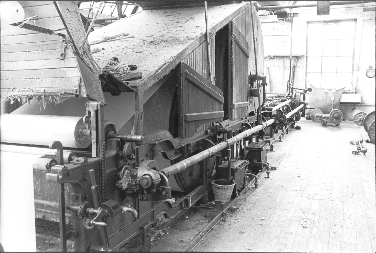
Picture number 10. negative number 7718021.
This is a picture of the 56 inch tape which is the one nearest to the door. We are looking down the side of it towards the place where the taper usually works at the far end, the place where the warps are delivered. In the left hand corner you'll see the web of warp going in. This tape was stopped at the time so the rollers at the front aren't forcing the web down into the sow box which was full of boiling size. The immersion roller is raised up on the rack. The immersion roller used to push the web down into the size, and of course the web was coated as it went through. You can see the drain cock at the side of the sow box and the drive which comes up from the far end to drive the rollers in the sow box. There is also another remote lever to control starting and stopping. It's important to realize that the bottom roller in the sow box and the drive to the weaver’s beam on the front of the tape are the only two things that are driven on this tape. The drums aren't driven. This makes these very old fashioned tapes, the only thing that drove the drums was the tension of the warp going round them. You can faintly see the first drum and the second drum through the open doors in the side of the tape. There are two drums, a large one and a small one. The arrangement was that the warp went from the sow box, right up over the front side of the big drum, down round it, up the back and over the top of the small drum coming backwards and then down and round that one to the bottom and then right the way underneath the tape to the front where it went round another roller which can be faintly seen actually on this picture where it turns up into the bed of the tape itself at the front. More of that when we get to the front of the tape. The Bancroft tape room was always noted as being a very dirty place, not because the men that worked there weren't of quality but due to the fact that our tape room was understaffed and there just weren't the men available to do the job as it should have been done. These men were more concerned in turning out quality warps than keeping everything clean. Admittedly they could have perhaps done a bit more towards keeping things clean than they did but they took the view that they were there to do the essentials and who can blame them.
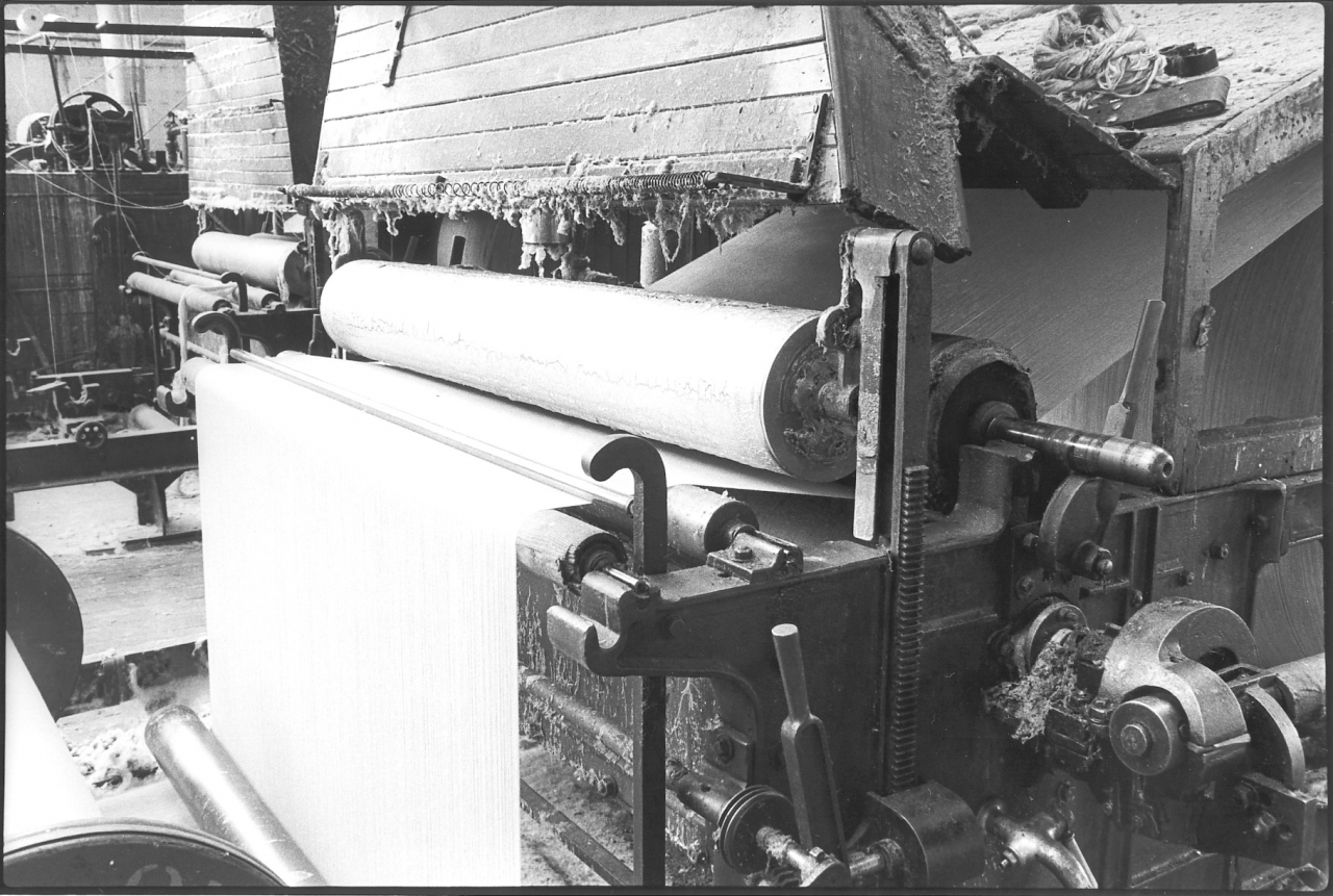
Picture number 11. Negative number 7718218A.
This is a close-up of the sow box, showing the web going in. It shows clearly the copper immersion roller. Everything that came into contact with the size was either cast iron or copper because anything else was eaten away at a tremendous rate. The size was very heavily corrosive. I should think it was acidic. The immersion roller is brought down by a rack which can be seen there. The roller behind it, which seems to be covered with felt on the outside is the squeeze roller which was a very heavy roller covered with taper’s flannel. This was dropped down by means of that cam which is supporting the spindle end. It dropped on to the top of a copper roller below, the warp sheet passed in between them and that roller squeezed the excess size out and allowed it to run back down into the sow box once the warp sheet had passed through. The wooden trunking above is an arrangement to catch all the steam that rises off the drying warp sheet and draw it away. There were fans in the top of it and they blew out to the atmosphere. While the tape was running air was being drawn up that trunking all the time and blown out at the top to keep the atmosphere in the tape room as free of steam as possible.
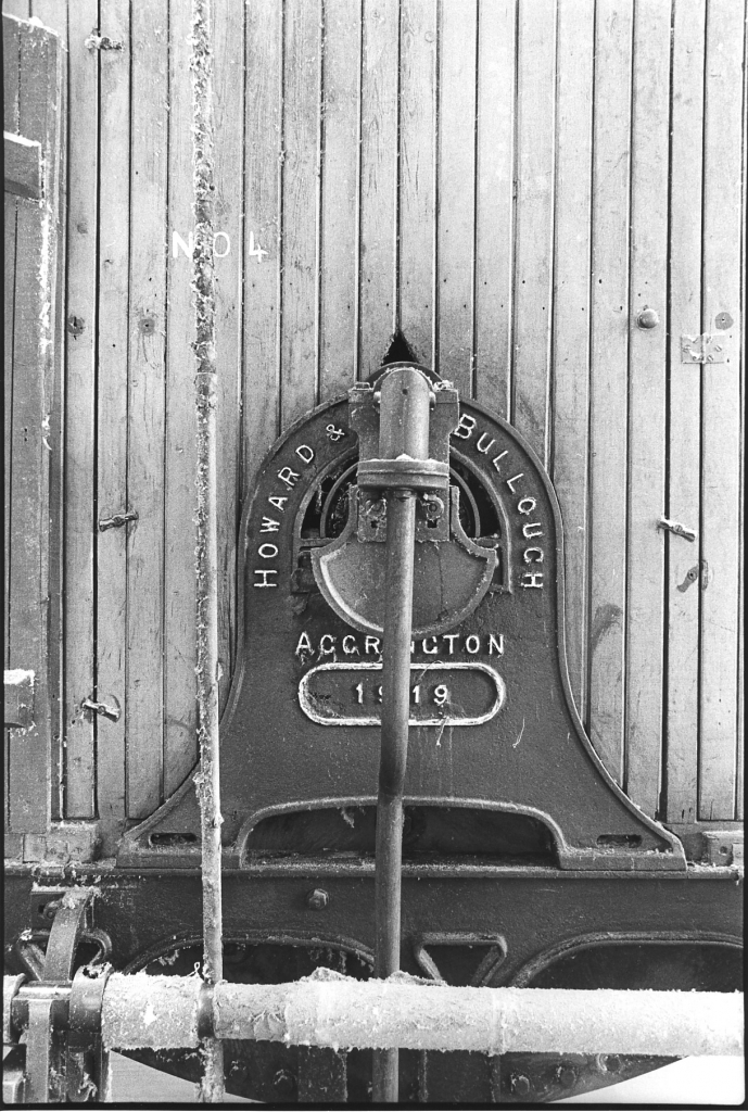
Picture number 12. Negative number 7718220A.
This is a picture of the side of the 56” tape which is the one we are looking at. It clearly shows the maker's name and the date it was manufactured. Howard and Bullough, Accrington 1919. This tape was new when the mill was built. The other, narrower tape was dated 1903 and so was second-hand when it was installed. Note the massive construction of the cast iron frame. This is actually the suspension point for the large drying cylinder. The pipe that’s coming out there is actually the drain from the cylinder. Obviously if you are putting steam in there is going to be condensation in the cylinder which has to be removed. The sharper ones amongst you might be wondering how the condensate was removed from the centre of the cylinder. A good question, it fooled me for a long time. I have never seen the inside of the cylinder but people who have tell me that inside there were copper vanes on the periphery of the cylinder which caught the condensate and carried it high enough to discharge by gravity down gutters on the side plate to this central point where it ran away via the drain pipe.
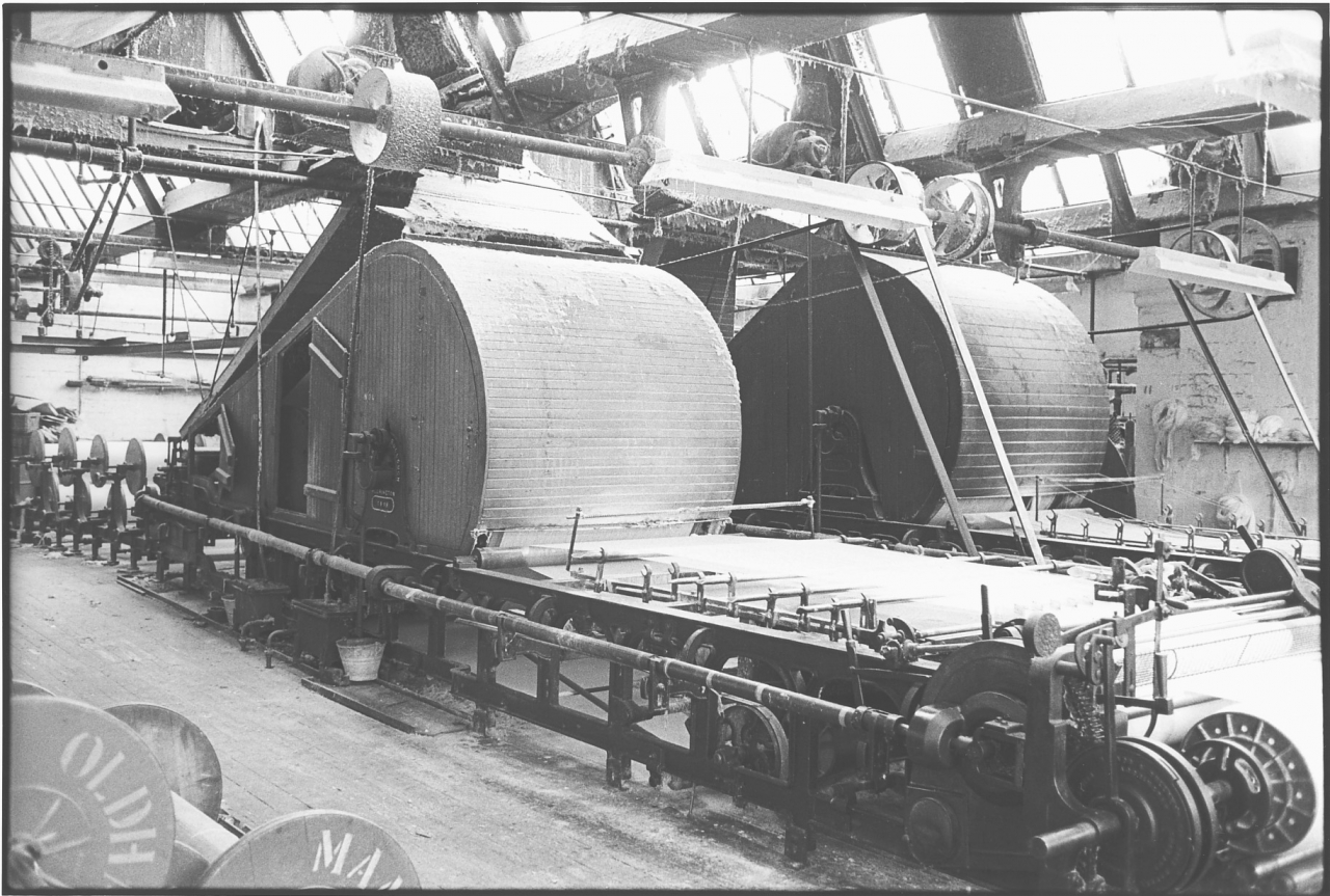
Picture number 13. Negative number 7718222A.
This is an overall view of the tape room and the two tape machines. Clearly to be seen is the driving shaft over the top. Notice that the pulley at this end is covered with dust, that's because that was the pulley which drove the third tape which used to be installed in here, there used to be three machines. One tape machine is usually reckoned to be enough to keep 400 looms going, and so when it was a 1200 loom shop there'd be three tape machines in. Notice again the north light construction, the lack of cast iron pillars, the fact that everything is belt driven and the very complicated arrangement on the headstock of the tape where the yarn is actually split, sorted out and delivered to the weavers beam which can be seen in the bottom right-hand corner of the picture, so as to make a good beam ready for going down into the warp preparation department and thence to the weaver.
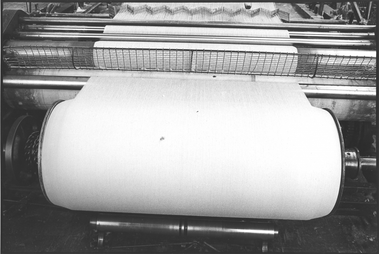
Picture number 14. Negative number 7718221A.
This is a picture of a weavers warp on the headstock of the tape ready for coming off. Interesting things to notice there are, starting at the top, the comb which delivers the individual threads to the warp evenly, the arrangement of rollers that the sheet goes round. Notice the big one covered with cloth, that's the drag roller that actually provides the power which draws the yarn through the tape, notice the guard to stop you getting your tie into the mechanism. And also notice that the beam itself, the web of warp going on to the beam seems to be narrower than the beam itself. This is what is known as a built-up beam and was done to get more yarn on to the weavers beam so that it could last longer in the loom. When it got so that the beam was actually full to the top of the flanges the comb at the top was progressively narrowed in and more and more yarn put on to build up. You'll see that it looks slightly curved at the ends. If you look at the bottom side you’ll see it plainly. It was possible to put an extra piece on that beam in safety. Obviously if they had kept it at the original width there would have been a danger of the threads coming over the flange so they used to build it up during the last piece as it was coming off. The rollers at the bottom, the shiny iron rollers at the bottom, opened out to the full width of the beam and used to run just inside the flange. They were press rollers and their function was to press the yarn as it went on, iron it down, roll it to make sure you got it all on perfectly firm and even.
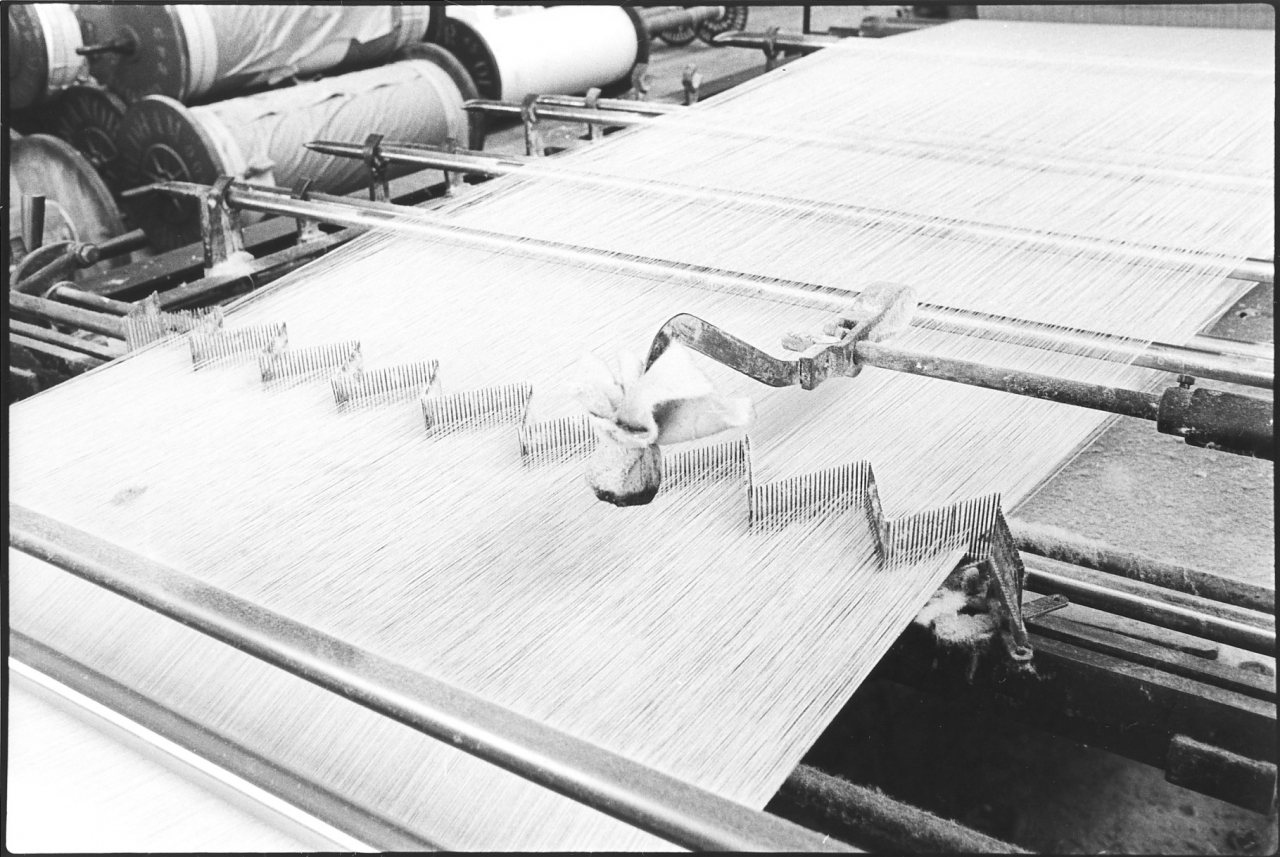
Picture number 15. Negative 771823lA.
This is an overall view of the comb on the headstock that guided the web of yarn on to the weaver’s beam. The bars which split the individual threads can be seen mounted across the frame, more of those later. Notice that the comb is on a sort of lazy tong arrangement. The idea of this is that the threaded rod below, when turned, narrowed that comb or widened it which enabled the taper to control the width of the web going on the beam. The weighted lever with the padded end that you can see at the front of the comb was the cut marker. The padded end looks slightly black on the bottom side, that is soaked in blue dye and what happens is that there is an automatic measuring device on the tape which, when it comes to the end of a piece, which is 100 yards, flicks that down. It drops down and hits the yarn and puts a mark on the yarn which shows the weaver that she is at the end of a cut and that should then be cut out and sent into the warehouse. Actually the two tape machines were different. This one had a single cut marker, and the older, smaller machine to the right of this had a double cut marker so that whether a warp had two cut marks or one cut mark told you which tape it had come off.
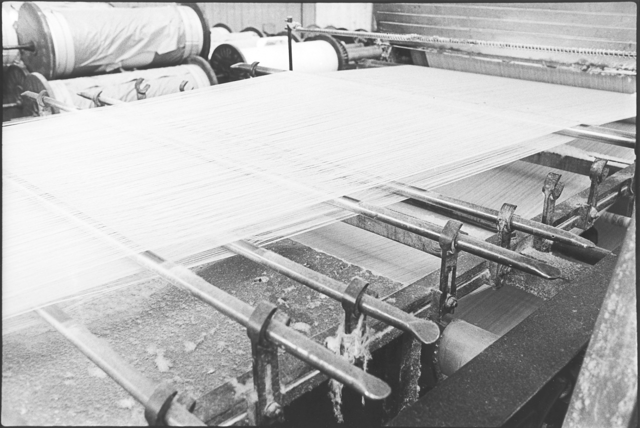
Picture number 16. Negative 7718229A.
This is part of the same series and shows very clearly the arrangement of the rods passing through the yarn to split it as it comes away from the drying cylinders. More of that later when we see the splitting bands being put in.
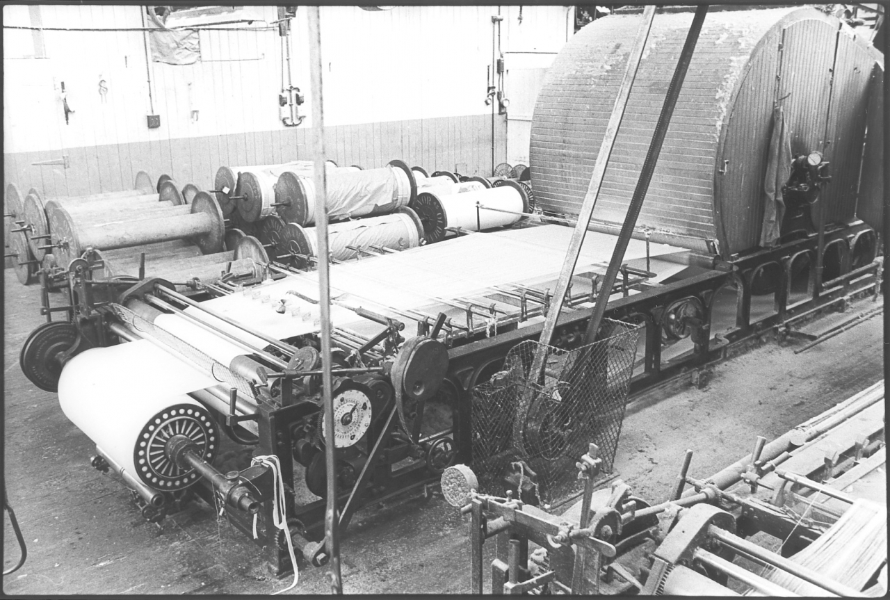
Picture number 17. Negative number 7718227A.
This is an overall view of the front of the tape giving a clear idea of the complicated nature of the front of a tape machine. There is a full warp on this machine. The picture was evidently taken when it stopped at week-end ready for that warp being taken off on the following working day. A taper always stopped with the full warp on, they never stopped half way through a warp because that automatically meant trouble for the weaver. It is important that whatever the quality of a warp it should be the same right the way through so that once the loom has been set up for it it will run right the way through. Notice the drive, one big leather belt down on to the main driving pulley of the tape guarded somewhat inefficiently by that piece of wire mesh. The lack of guarding at Bancroft is a thing that always used to amaze me, and yet we never had any accidents.
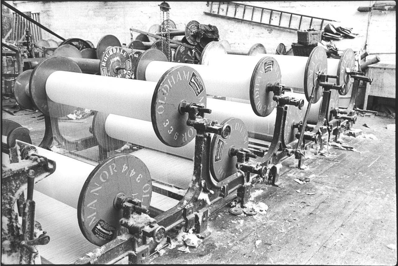
Picture number 18. Negative 7718228A.
This is an overall view of the creel from the other side. I don’t think there is anything on here that we haven’t already discussed. It just gives you a very clear idea of the construction of the beams themselves. Notice that the arrows pointing to the rotation of the beam are pointing the opposite way to what they're rotating here. This doesn't mean that there had been a terrible mistake made. That arrow is actually an instruction to the beamer, that the beam must rotate that way when the beam is being wound. It doesn’t apply to the taper obviously, when the taper's taking it off it is running in the opposite direction. Notice the cast iron frame, cast iron construction and the fact that everything is covered with dawn. This flies about all over the place, it’s not only limited to carding rooms and places like that.
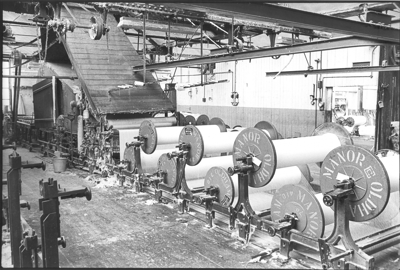
Picture number 19. Negative number 7718019.
This is again an overall view of the tape but from the back corner and looking forward. Notice that above the trunking leading up to the fan is a bar with some rods on, with bobbins of thread on. That’s another small creel and was used if either there’d been a mistake and there wasn't just enough ends in a warp, it was possible to lead some more in from there. Or if they wanted to strengthen the outside edge for a selvedge they'd put a couple of extra threads in down each side. You’d very often see that being done when they were running.
Picture number 20. Negative number 7718834.
This is a picture of one of the size becks. The size becks are a wooden construction, cast iron frame and lined with stainless steel. In the old days they wouldn’t be lined, they were completely water tight but over the years they deteriorated so they have been lined with stainless steel. The arrangement on top is the belt drive down to the gearing which drives the paddles inside the size boxes. These paddles keep the size in motion when it is being boiled or being used by pumping it over to the sow box on the tape. If the paddles weren’t operating it would settle like porridge. Each size beck has its own water supply and steam supply and the method of using them is that size is drawn off one box, there are two boxes here, left and right, size is drawn off one box to feed to the tape and at the same time a fresh supply is being boiled up in the other box so that there is a continuous supply. When one side's finished the pump can he swapped over to draw off the other beck.
The method of making size is to, in our case at Bancroft we used to use farina which is potato starch, pure tallow and sometimes a bit of soft soap. Occasionally a bit of size used to be added. We used very simple mixes of size, and the idea is to boil it together until the starch granules burst and go into a jelly and this means boiling it for about an hour or two hours. The size becks were great users of steam. They were very expensive to operate. There are actually two sets of size boxes, one for each tape. Each tape has its own separate size box as sometimes the tapes are running on different size mixes. The pipe for feeding the tapes can be seen going off to the right, the nearest one to us is going to the far tape and the far pipe you can see off the far set of size boxes is going to the nearest tape, the one nearest to us here.
Size is quite good stuff when it's first boiled up but believe me, when it has stood over the summer holidays or something like that it stinks terribly. Some of the most terrible smells you can imagine could he found in the tape room after the long break when they first boiled it up. I couldn't really see how it ever did anybody any good working up there but they seem to survive to a fair age. Notice again how dirty everything is. Things were dirty up there, there is no doubt about it, but in a lot of ways things were sadly neglected. It was none of my business to clean up in the tape room, but I often used to wish that they'd just taken a little bit more trouble over cleaning up. Any maintenance that had to be done up there was a very dirty dusty affair and was certainly not to be looked forward to. Notice that the trunking which carries the steam away from the box on the far size box is wooden, and the one on the near size box is aluminium. The reason is that the wooden one is original, it's the easiest way of making a trunking. The near one is a modern edition. Evidently the old wooden trunking has broken down and so a modern aluminium one has been substituted for its far cleaner and far more efficient and less likely to get furred up on the inside or warp and split.
One interesting thing about this picture just before we leave it is that it gives an idea of the sort of antiquated worn out machinery which was used at Bancroft. And yet the results were superb, mainly due to the fact that the men who were using this machinery were experts and knew their job inside out. The thing about the tapes at Bancroft was that it's doubtful whether anybody else could have run them. It would certainly have been a long job training anybody else to run them. A weaving shed can’t work efficiently without good warps and the fact that Joe was getting near to retiring probably means that Bancroft couldn’t have lasted longer than him. In fact at the far end we only had one taper, Joe, and we were all very much aware that if he was off poorly the mill stopped. In point of fact it never happened, but that would have been the case.
SCG/19 September 2003
7,017 words.
LANCASHIRE TEXTILE PROJECT
TAPE 78/AI/09 (Side one)
THIS TAPE HAS BEEN RECORDED ON MAY 1ST 1979 AT 13 AVON DRIVE BARNOLDSWICK. THE INFORMANT IS STANLEY GRAHAM WHO WAS THE ENGINEER AT BANCROFT MILL AND WHO HAS BEEN THE INTERVIEWER ON MOST OF THE TAPES..
We are carrying on with the description of the folio of pictures on taping.
Bancroft folio, tape picture number 21. Negative number 7720504.
What we are going to describe now is the process of starting a tape up, from the end of one production run to the beginning of the next. In other words to when the first warp comes off the new set, from then on it is repetition, the warps come off in sequence. It's only a matter of watching the machine, and making sure that all is running properly, taking full warps off as necessary until the back beams run out and the whole process starts again.
The two people working together here are Joe Nutter the taper, and Jim Pollard the weaving manager. This is a good indication of the way Bancroft ran. I should explain that really, in a tape room with two tapes or even with one tape in, there ought to be a taper and a tape labourer. The tape labourer's function is to keep everything tidy and to give the taper a hand whenever he wants it. Many of the jobs on a tape, especially in setting up, which we are going to describe now, are two handed jobs. Bancroft hasn't had a tape labourer for some considerable number of years because what happened was that when there were two tapers and they used to labour for each other. It was very seldom both tapes were out at once; and if they were it was no great matter, it meant one stood for a bit while they got them both ready. The tapers got paid extra for this but it saved a full wage. When we got to the stage where we only had one taper Norman Grey, the other taper, went off sick as we were weaving out and never returned to work], Joe, it meant that somebody had to go in from outside to help and of course this was always the old stand-by, good old Jim, the weaving manager, who used to do every job in the mill. He was capable of doing every job in the mill. So in this sequence of photographs, Jim has the white shirt on with rolled up sleeves and Joe has a knitted shirt with short sleeves.
Picture 21. When a set of back beams runs out they’re never exactly the same length and one beam always runs out before the others so there is a certain amount of waste left on most of the beams. The first thing to do is to cut this off and the easiest thing to do is cut it off while it's in the creel. The method is to run a sharp knife down the beam and the waste all comes off as short lengths. Jim’s cutting a beam out here. This process is what is known as cutting a set out. Jim used to save this unsized waste cut into short lengths for me to use on the engine for wiping down. It is worth mentioning here that if you have read the spinning tapes you will remember that one of the processes in conditioning the fibres for spinning is to impregnate it with a small amount of oil and water to make it more elastic. This meant that the soft waste used in the engine house was no good for polishing because of the oil content. It also explains why cotton waste helped preserve the polished finish on the steel, it always left a minute quantity of oil on a surface that had been wiped down. Another point is that this is also one of the reasons why size penetrated the yarn in the sow box better if it was boiling furiously.
[This is a good place to alert you to the fact that when I was doing a series of pictures describing a process they are all shot on one roll of film. This was necessary to preserve continuity. In case you’re wondering how I could leave the engine for so long, I had a good firebeater who would sit with the engine and watch the oils while I was away doing the pictures. I would pop back down occasionally to make sure he was all right but we always had all our bases covered.]
Picture number 22. Negative number 7720508.
When he's cut all the waste off the beams Jim cuts the sheet about 2ft below where it goes into the sow box and leaves those ends dangling in two bunches. These bunches are used for tying the fresh sheet on when it goes through the machine.
Picture number 23. Negative number 7720507.
While this in going on Joe is sorting his beams out and getting the block and tackle, and the spreader ready to lift the beams in or lift them out as the case may be. Some beams are relatively light and are lifted out by hand when they are empty but in this case, these are fairly heavy beams being Manor and solid wood and so they are being lifted out with the gantry.
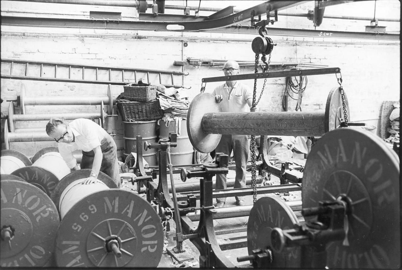
Picture number 24. Negative number 7720511.
Joe's lifting the empty beams out while Jim wheels full beams to a position where it will be fairly easy to get hold of them with the block and tackle to lift them in.
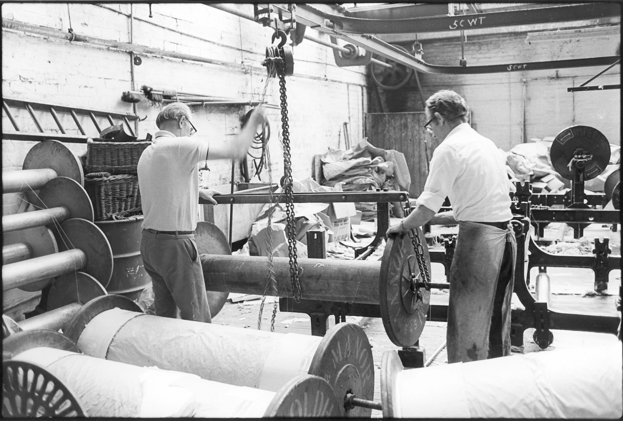
Picture number 25. Negative number 7720514.
This is a picture of them both at work lifting empty beams out.
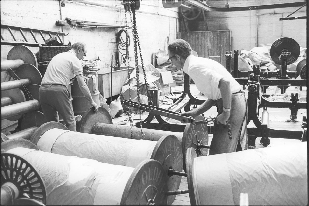
Picture number 26. Negative number 7720515.
This shows them dropping the empties on the floor from where they’re carried away by hand or wheeled away on the truck, and then disposed of afterwards. One of our big troubles was that our transport men, the people who did our transport for us, were always a lot happier when fetching full beams in than taking empty beams out and we used to finish up with a lot of empty beams around which got under our feet and didn't help the spinners either because of course they wanted them back as soon as possible. There was a good reason for this from the drivers point of view. He wanted a full load of empties for one mill as this was the most efficient way of taking empties back. Notice that all the beams are wrapped with brown papery and a band of corrugated paper at the end. On this picture you can see the reason for that on the first two beams nearest to us. When the beams are stacked on the wagon obviously the flanges are going to rest on the cotton in some places and if there's a layer of corrugated paper like that it means that the flange isn't going to have any damaging effect on the warp underneath. You can see the marks the flanges have made on the paper protecting the yarn.
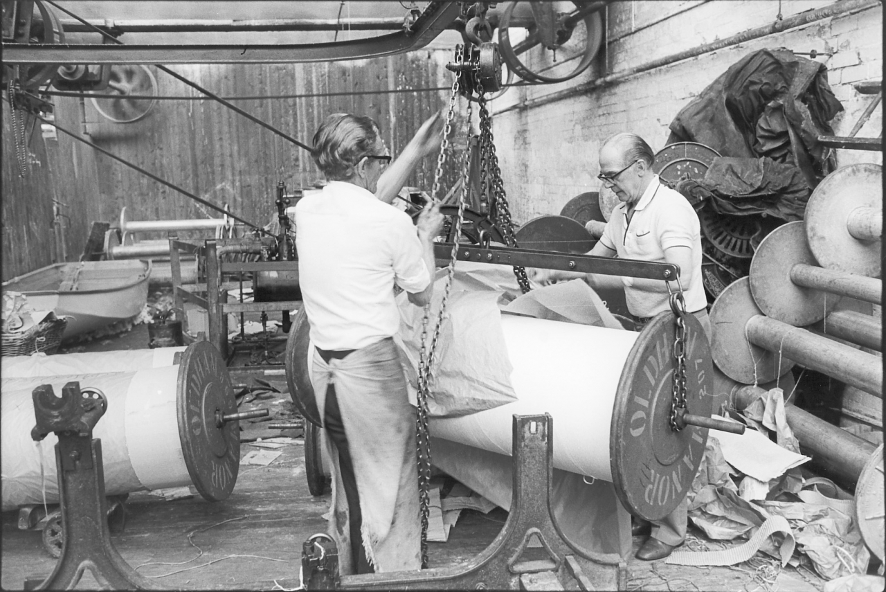
Picture number 27. Negative number 7720401.
Here they have picked a full beam up. Jim is winding it up to get it high enough to pass over the stanchions in the creel and Joe is stripping the brown paper off and throwing it on the floor behind him where it will remain for some period of time.
Picture number 28. Negative number 772040A.
Very similar. Jim’s nearly got it up to the top now.
Picture number 29. Negative number 7720402.
The paper's off and he is still lifting that beam up and he has nearly got it to the top. This in all hand work of course which is the reason why that chain on that block and tackle was so highly polished.
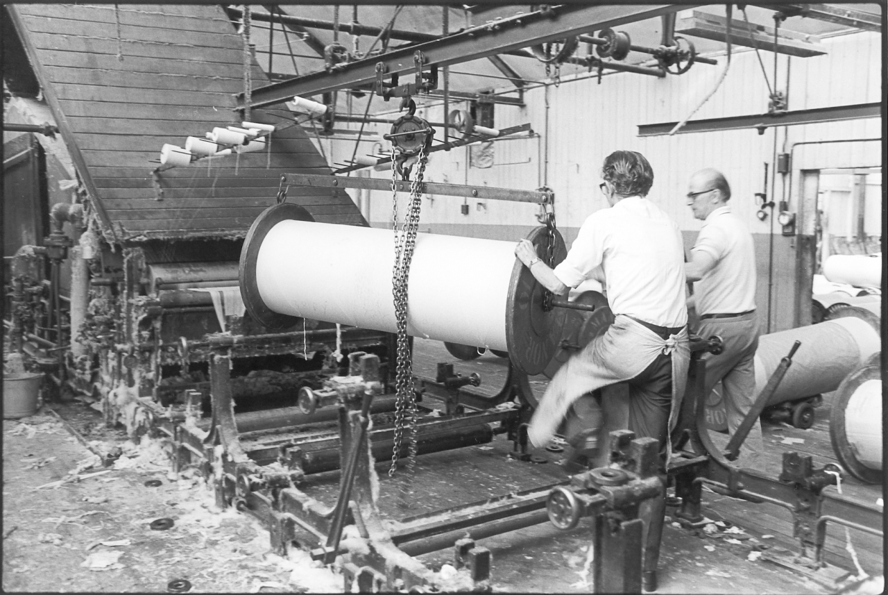
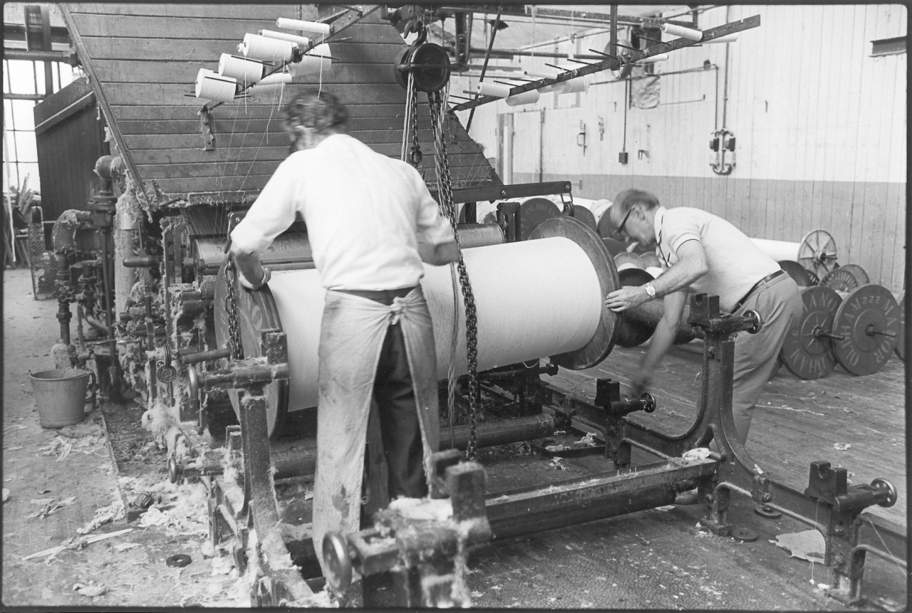
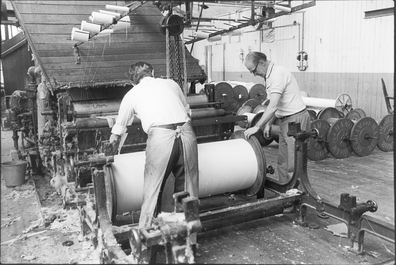
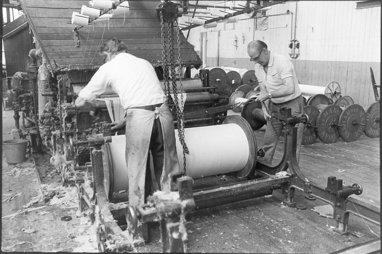
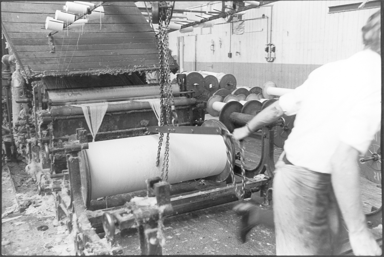
Pictures number 30/36. Negatives number 7720403/10.
This series of pictures follows them in to the creel, lowering the beam in to position and returning for the next beam. This process is repeated until the requisite number of back beams in that set are in place in the creel. They're all put in in a special way with their ends facing each other so that they
can be knotted up together to be drawn through.
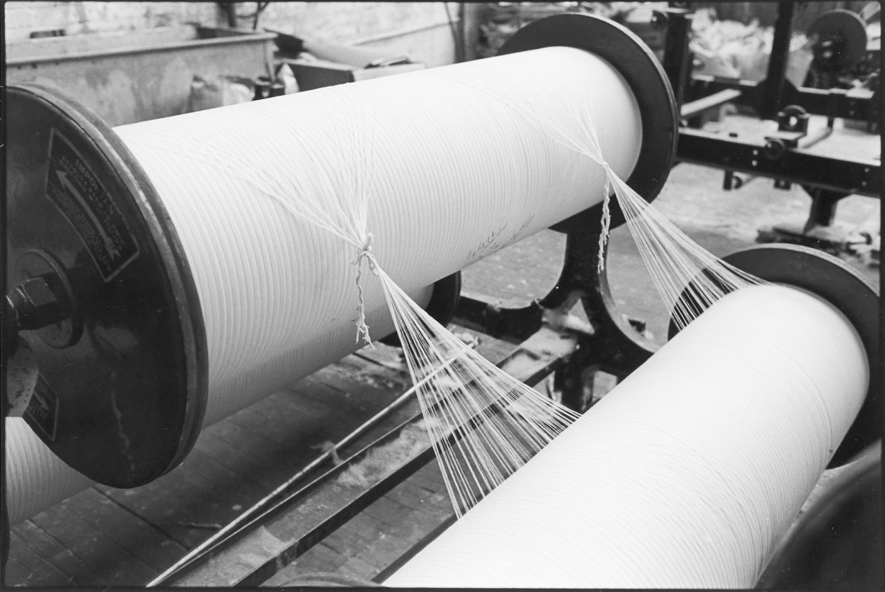
Picture number 37. Negative number 7719105.
They take the ends and divide them into two bunches and knot them together on adjoining warps. You'll notice that those two warps wind off facing each other. This applies to the first two in the set nearest the sow box, the next two back and so on right the way back. If there's going to be an odd one as there is in this case it's the one at the back. Having knotted them all together like this, light steel rods are taken and dropped on the joined sheets between each pair of mating beams. These are used to drag the ends forward for joining to the old sheet, we’ll see this in a minute.
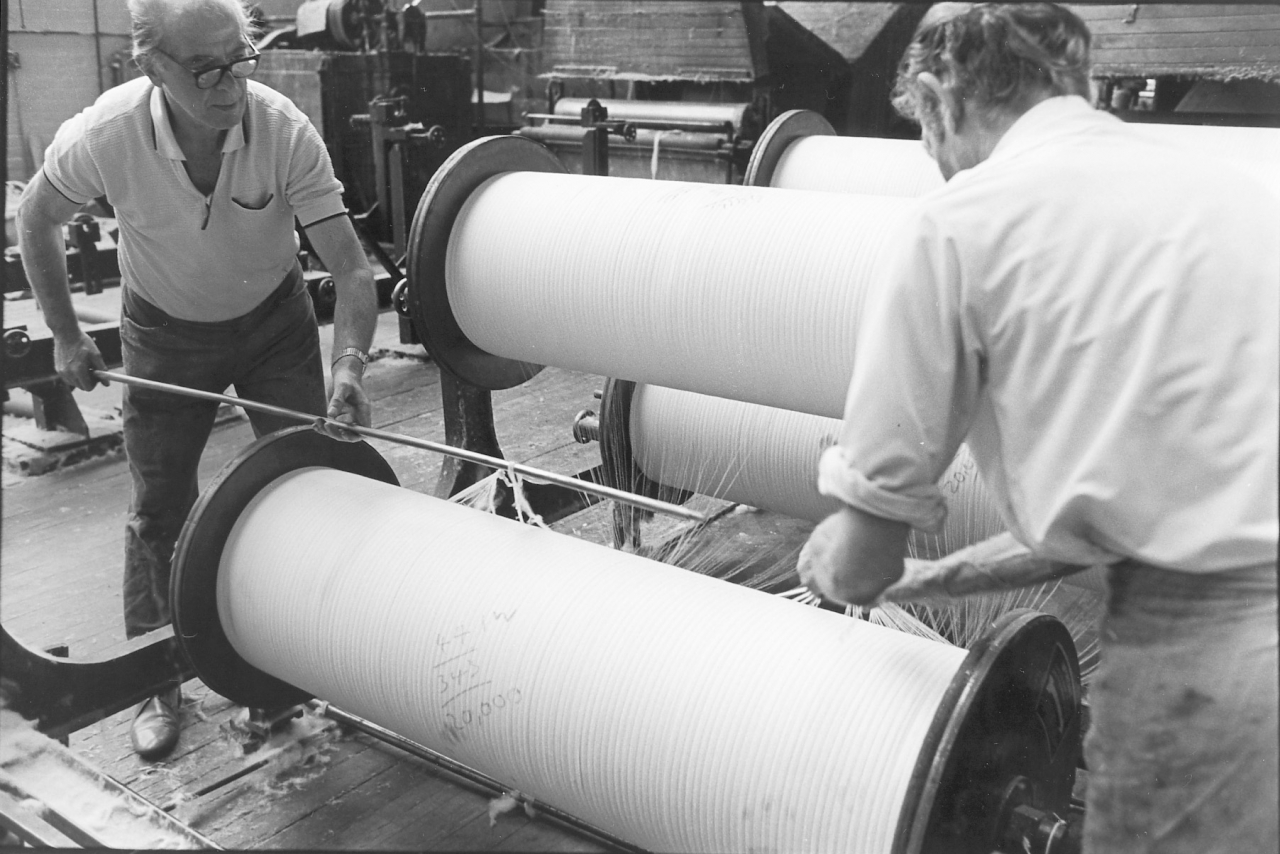
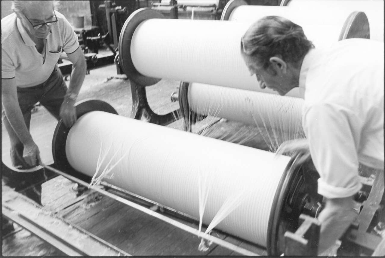
Pictures 38 and 39. Negative numbers 7719106/07.
This shows Jim and Joe dealing with the odd beam at the back by passing the rod through the web on the back beam. Notice the beamer’s marks on the surface of the yarn; 44IW/343/20000. This means that the yarn is 44s count. IW is the type and quality code, 343 is the number of ends on the beam and 20,000 is the length in yards.
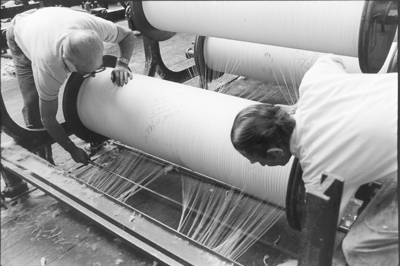
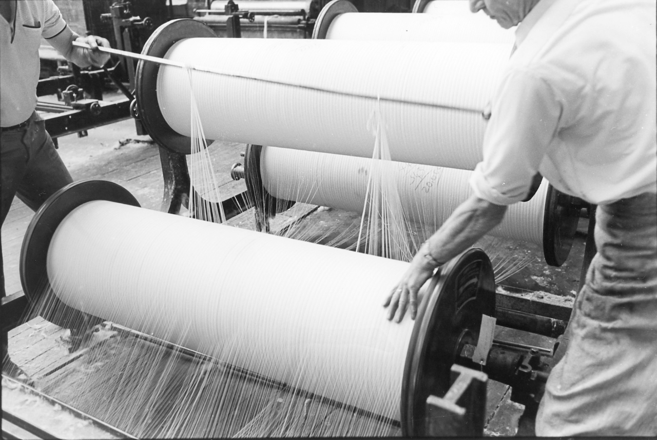
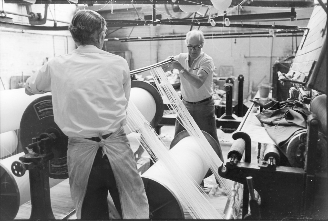
Pictures 40/41/42. Negative numbers 7719108/09/12.
These pictures show them using the light steel rods to pass the sheet round the back roller of the creel and bring it forward under the beams gathering all the ends up as they go until they have passed the complete sheet under the front roller of the creel. In the last picture they are drawing sufficient length up at the front to accomplish the next step.
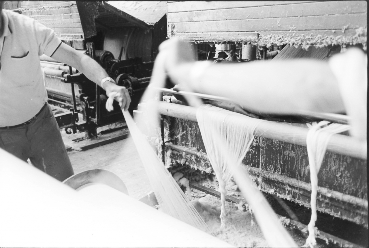
Pictures 43/44. Negative numbers 7719113/16.
Here you can see the next stage. All the ends are gathered together, pulled up, cut off level and then tied into a knot. Then this knot, this bunch of ends is tied on to the bunch of ends of the old sheet which is hanging through over the wooden roller at the front of the sow box. You will see that they have split each side into two ends giving four small knots rather than two large ones. At this point the ‘gaiting’ of the tape departed from normal practice. Normally nothing needs to be done to the squeeze roller but in this case the tapers flannel which covered the squeeze roller was getting a bit worn at the end and Joe decided that he was going to draw it back, make it square at the end and get it on the roller more evenly.
Picture number 45. Negative number 7719121.
Here you can see that some of the flannel has been dragged off that squeeze roller and is lying a lump on the front of the sow box. All the ends are knotted together ready to go in. Joe is turning the steam on there which will start boiling the size up in the sow box. You can see how dirty everything is at that end, it was really terrible. It takes a while for that sow box to boil up and while that was happening Joe and Jim dealt with the flannel.
Picture number 46. Negative number 7719123.
While the sow box is boiling up, Joe and Jim draw the flannel forward and cut it off to a square edge with a knife, starting in the middle. The damaged end is thrown away.
Picture number 47. Negative number 7719124.
They have cut that end off, they've got a straight edge left there hung over the front of the sow box. The back of the tape, the sow box end is ready now for starting up but before this can happen Joe has to prepare the headstock.
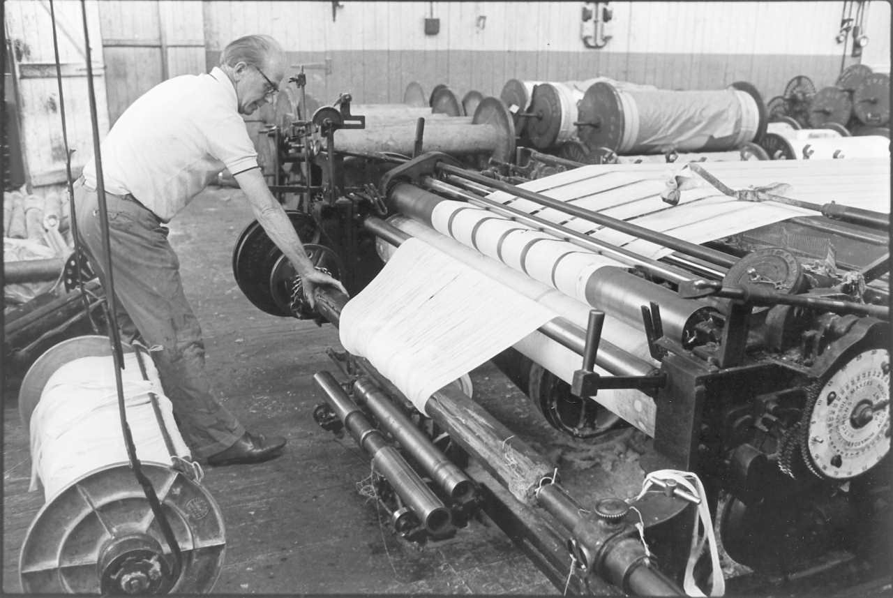
Picture number 48. Negative number 7719125.
Joe goes round to the front and takes out the weavers beam which was the end of the last production run. It’s there hung up behind him on the two leather straps. He has put on a waste beam which is a big beam with no flanges. He puts that in and wraps the lap of the old warp sheet round it. Now you must understand that all the cotton that is left in the tape, and everything that is on the new sheet until they have got it settled down and running is waste. It's a big waste of yarn but it's something that nobody has ever solved. Joe's putting the lap of the waste on to this plain roller at the front and that is going to draw everything through the machine when he sets it on. The sheet will come through and all the waste will wind on to this plain wooden beam. The first length of sheet that comes through has been sized and is hard and stiff but then the soft waste starts to come through. Joe balls that off when he empties the waste beam and saves it for me. This is the waste I use in the engine house for making the rope that lines the gutter round the engine beds.
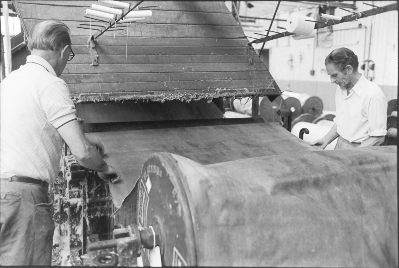
Picture number 49. Negative number 7719128.
We’re round at the back and Joe has set the tape on but very slowly. As the squeeze roller turns it draws the flannel on to the squeeze roller. The warp sheet is being drawn in at the same time.
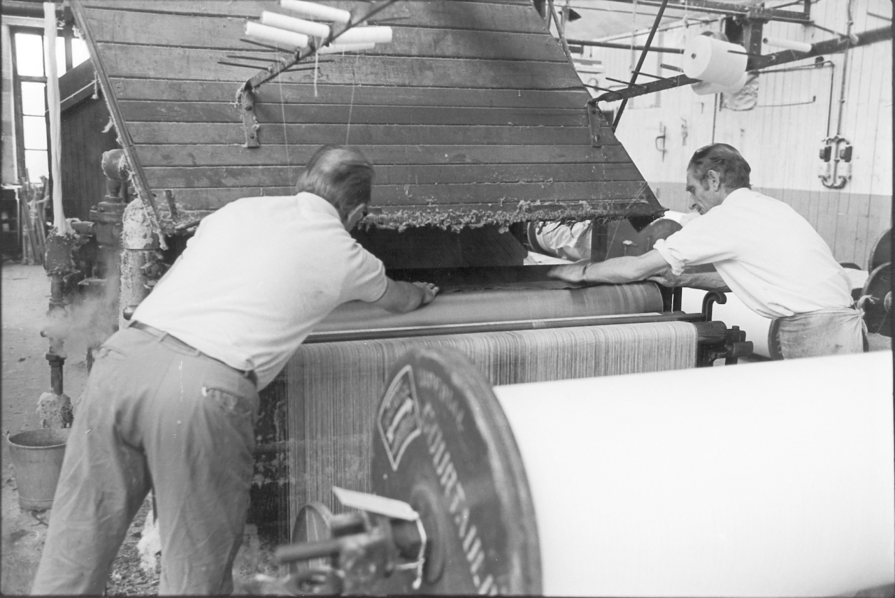
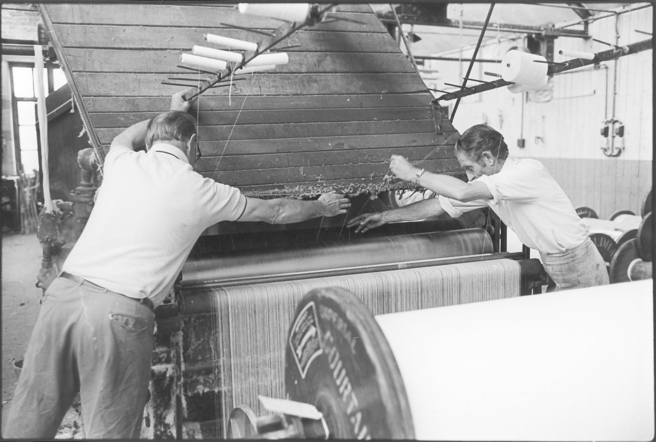
Picture number 50/51. Negative number 7719130/32.
Here we see that the flannel is completely wrapped round the squeeze roller and Jim and Joe have reached up for a couple of ends from the creel above them and are wrapping thread round the outside of the flannel. This is simply to stop the loose end flapping. Notice that the warp sheet has sorted itself out now into an even sheet over the whole of the roller in front of the sow box. Notice that the immersion roller has been dropped and the sheet is passing through the size. This wouldn’t normally be done at this stage but it has been dropped to give clear access to the squeeze roller.
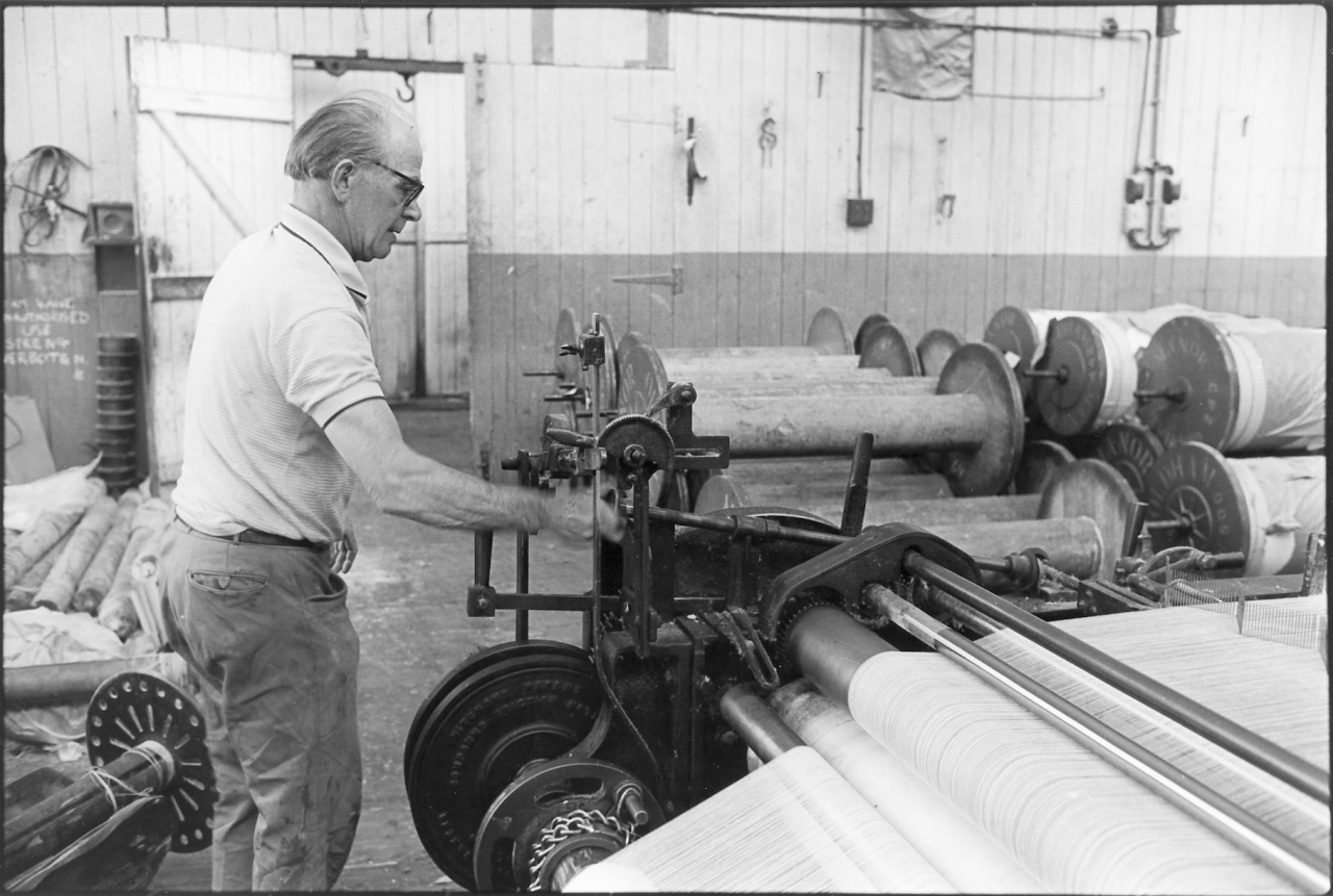
Picture number 52. Negative number 7719203.
Here Joe has gone to the headstock at the front of the tape and is making one or two adjustments to the width of the comb so that it winds evenly on to the waste beam, but also takes up its correct position across the whole width of the bed of the tape ready for the next stage.
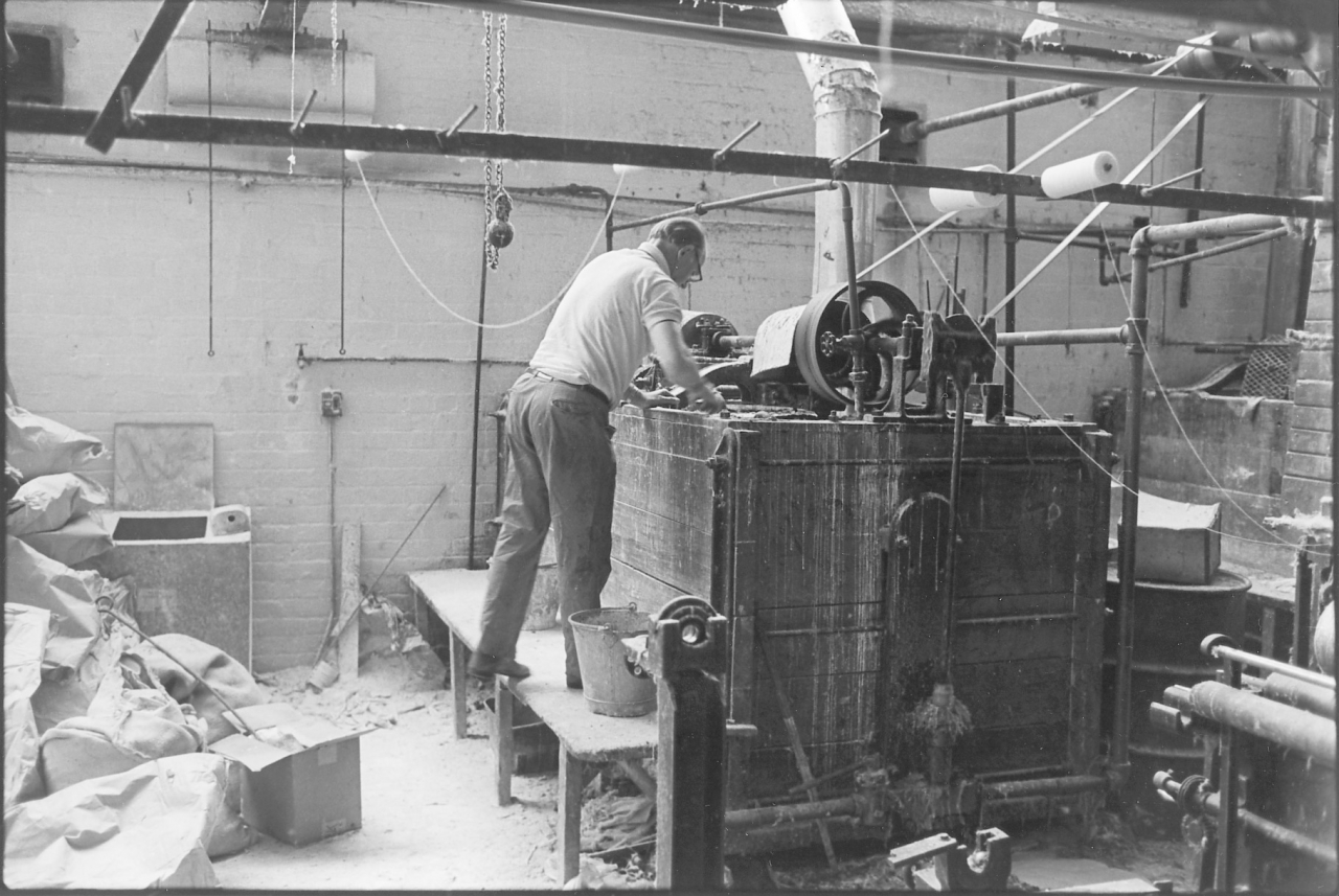
Picture number 53. Negative number 7719122.
On his way back to the creel end of the tape Joe has just popped across to the size beck to make sure that everything is all right there. He checks that the size is mixing, is the correct temperature and is being pumped over properly.
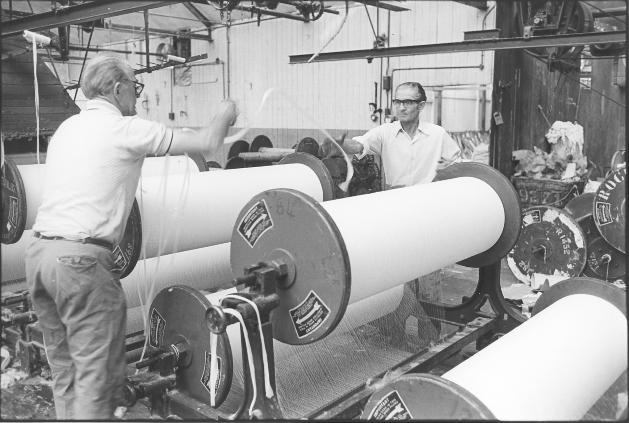
Picture number 54. Negative number 7719136.
Bear in mind that during all these pictures the tape is running very slowly. What Joe and Jim are doing here is throwing in the splitting bands. The purpose of these will become clearer later but for the moment recognise that during the sizing process the sheet of warp is glued together into what is effectively a wide tape. This is where the taping machine gets its name from. At some point these individual threads have to be separated. The splitting bands give a guide as to where the rods that will do this splitting have to be inserted. Hence the name ‘splitting bands’.
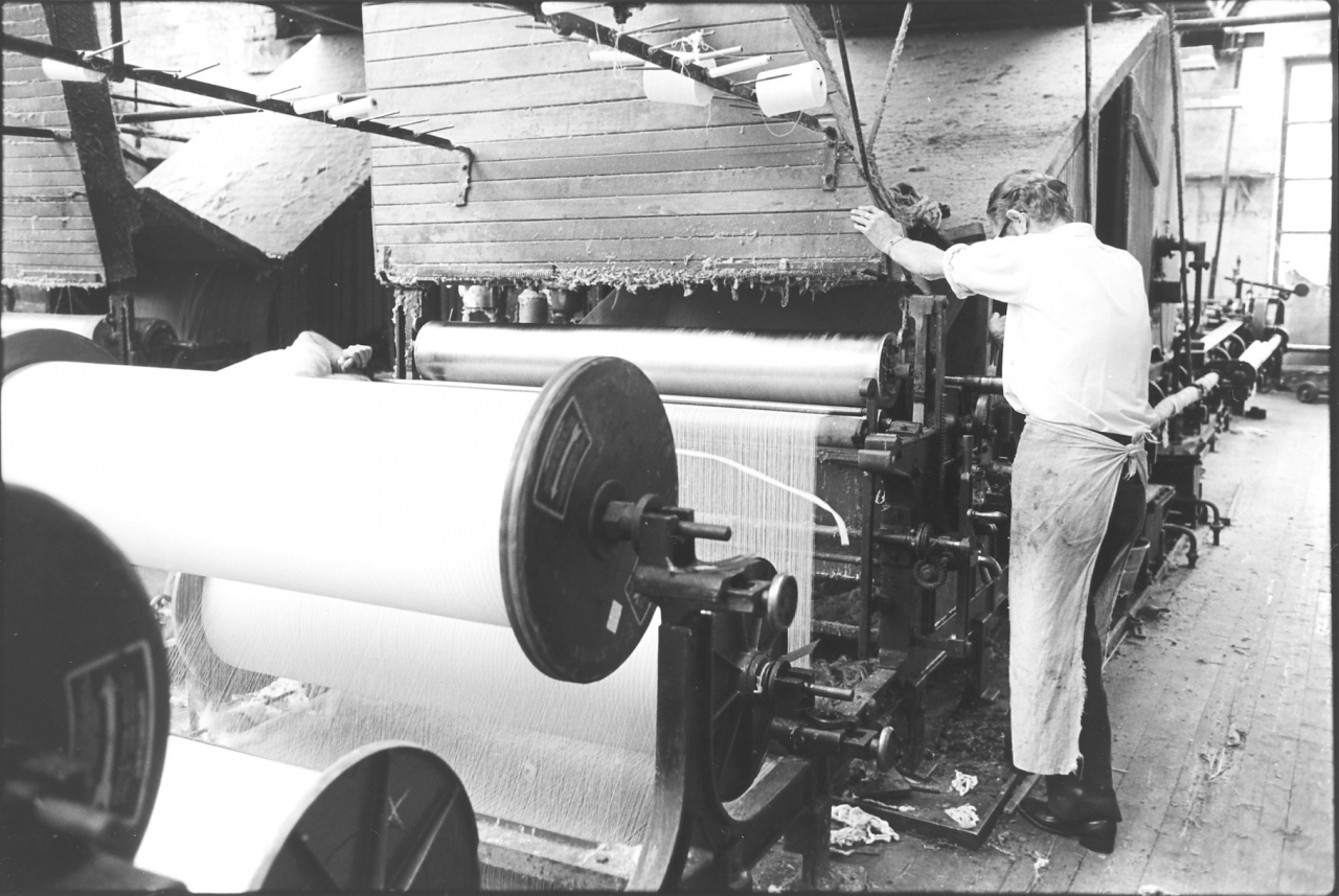
Picture number 55. Negative number 7719226.
Jim has raised the immersion roller so that the splitting bands can pass through the tape without being immersed in the size. The last of the splitting bands is climbing into the tape and I’m not quite sure what Jim’s doing on this picture. He seems to be resting his left hand on the trunking and his right hand is on the lever that controls the cam which lowers the squeeze roller. Joe is bent down making an adjustment to his steam supply to the sow box I think. As soon as the last splitting band has passed the squeeze roller Joe and Jim will operate the cams that drop the squeeze roller on to the warp sheet.
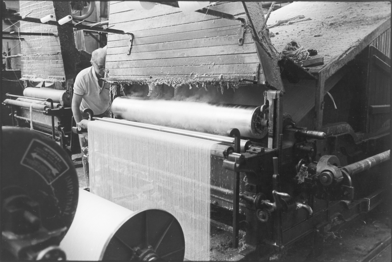
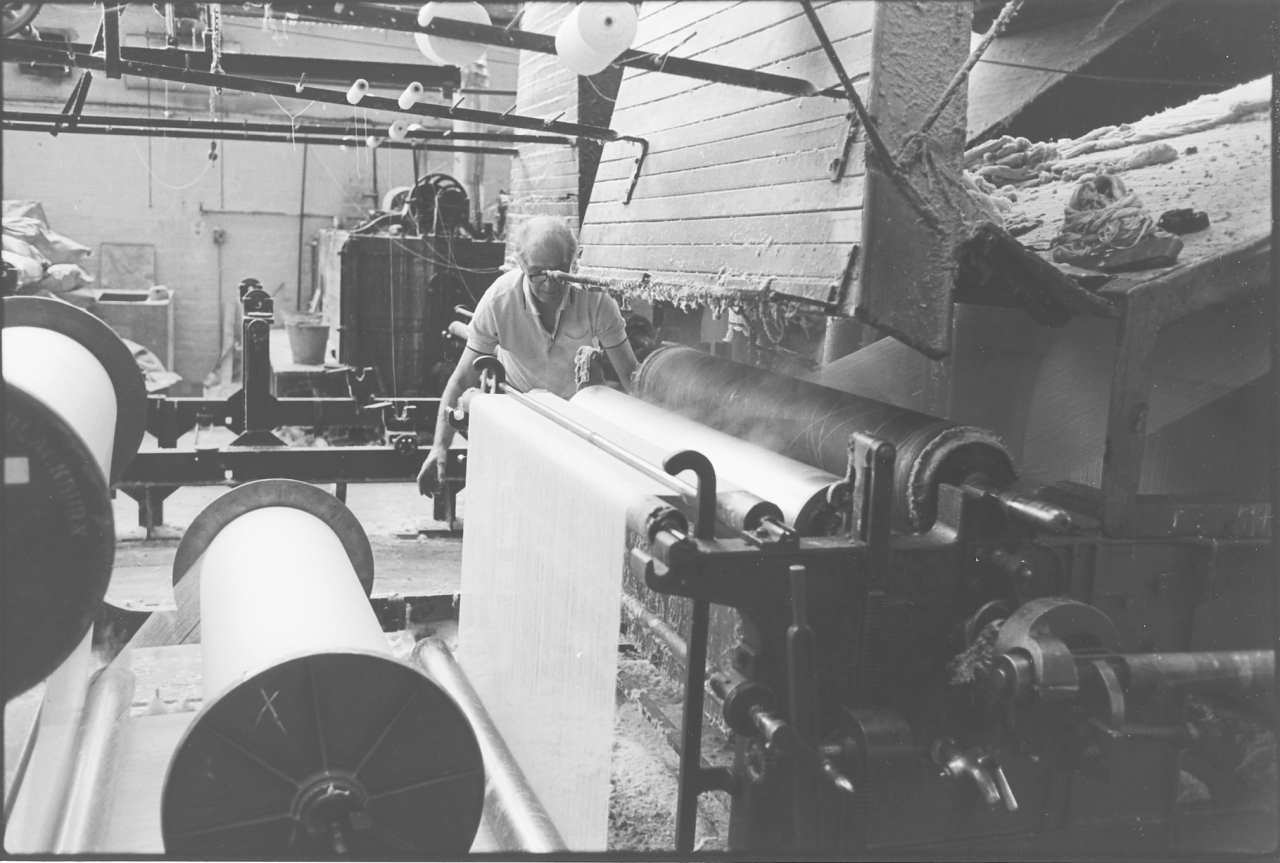
Picture number 56/57. Negative number 7719227/29.
Joe is about ready to drop the immersion roller. The squeeze roller's down and the immersion roller, that's the big copper roller at the front, is just going to be dropped into the sheet to force it down into the size. In picture 57 Joe has completely dropped the immersion roller and the sheet is now running through the size as it will do for the rest of this production run. Notice the steam rising through the sheet and being drawn up the trunking. The size in the sow box is now up to temperature and boiling well.
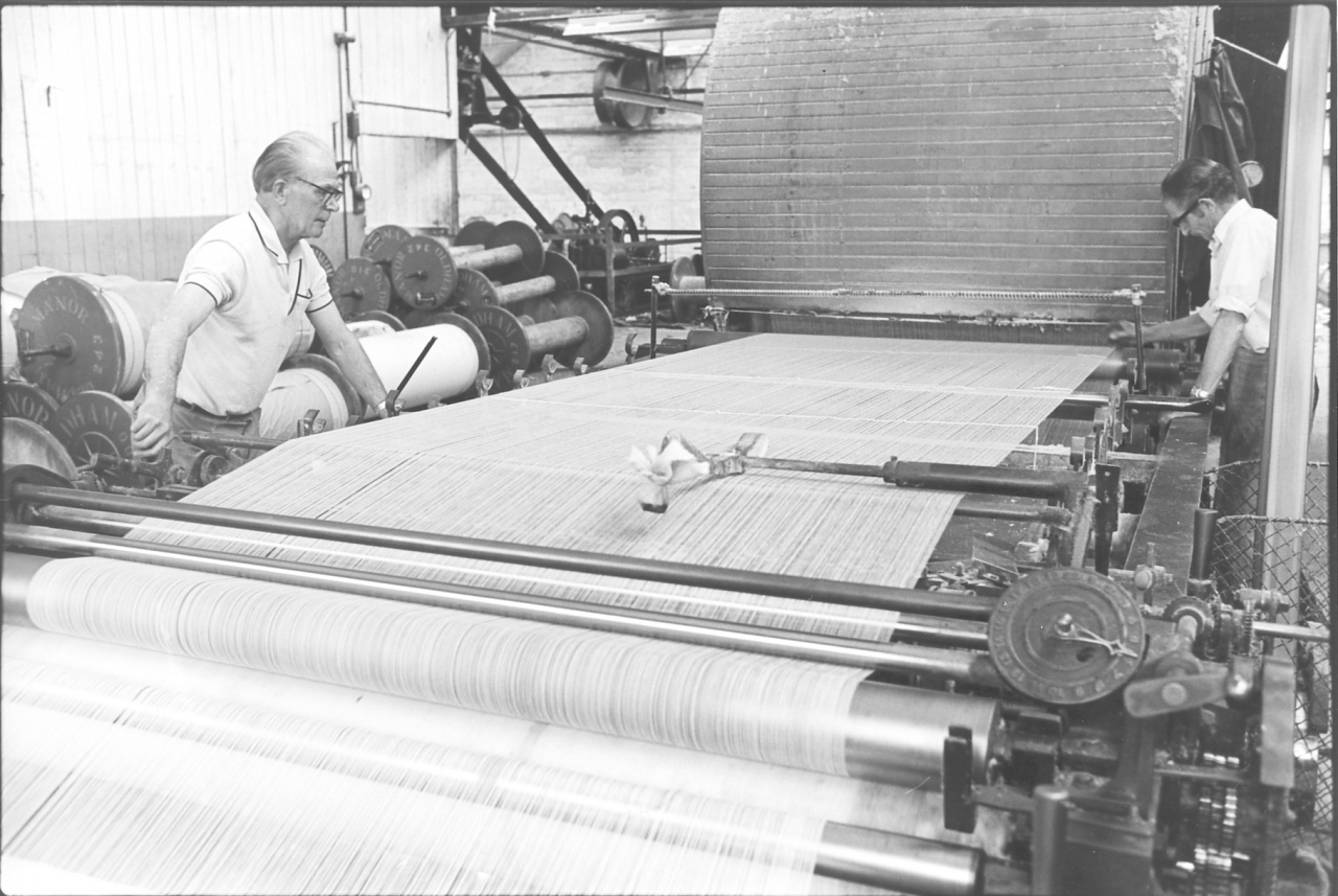
Picture number 58. Negative number 7719232.
Both Jim and Joe go round to the front now. Notice that a rod has been operated to lift the sheet clear of the comb at the front of the sheet. Jim has dropped a striking comb through the sheet up against the trunking. This ensures that the sheet is evenly spread over the bed and will be carried forwards by the sheet as it slowly advances. If you look carefully here you’ll see that there's a band coming through there. This band's there to denote the place where they started sizing and where they started on the run.
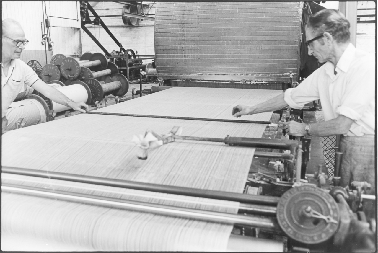
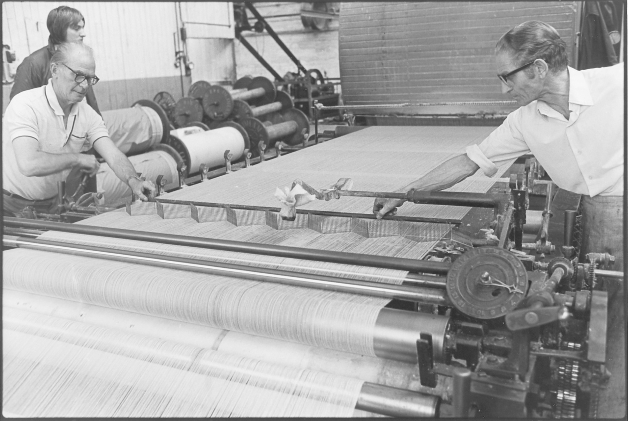
Picture number 59/60. Negative number 7719233/34.
Here you can see this comb coming down. It's a very fine comb and the reason for letting it come down like that is that the comb has made sure that, as near as possible, those threads are all evenly spread out across the tape. When they get almost up to the set of combs at the front that will split it while the machine is running, Joe drops the sheet on to the comb. If you look very carefully indeed, just in front of Jim's hand you'll see where a couple of the threads, and in fact another single one further on, have lodged on top of the teeth and haven’t quite dropped yet. They’ve just this minute done it, but they will drop of course. So now we have got the tape running and sized warp sheet is coming through but it hasn't been split, it's coming through in a sheet.
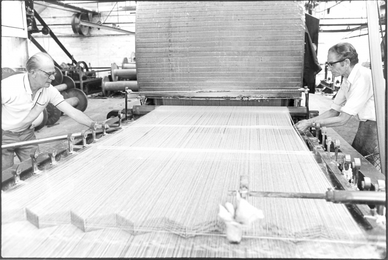
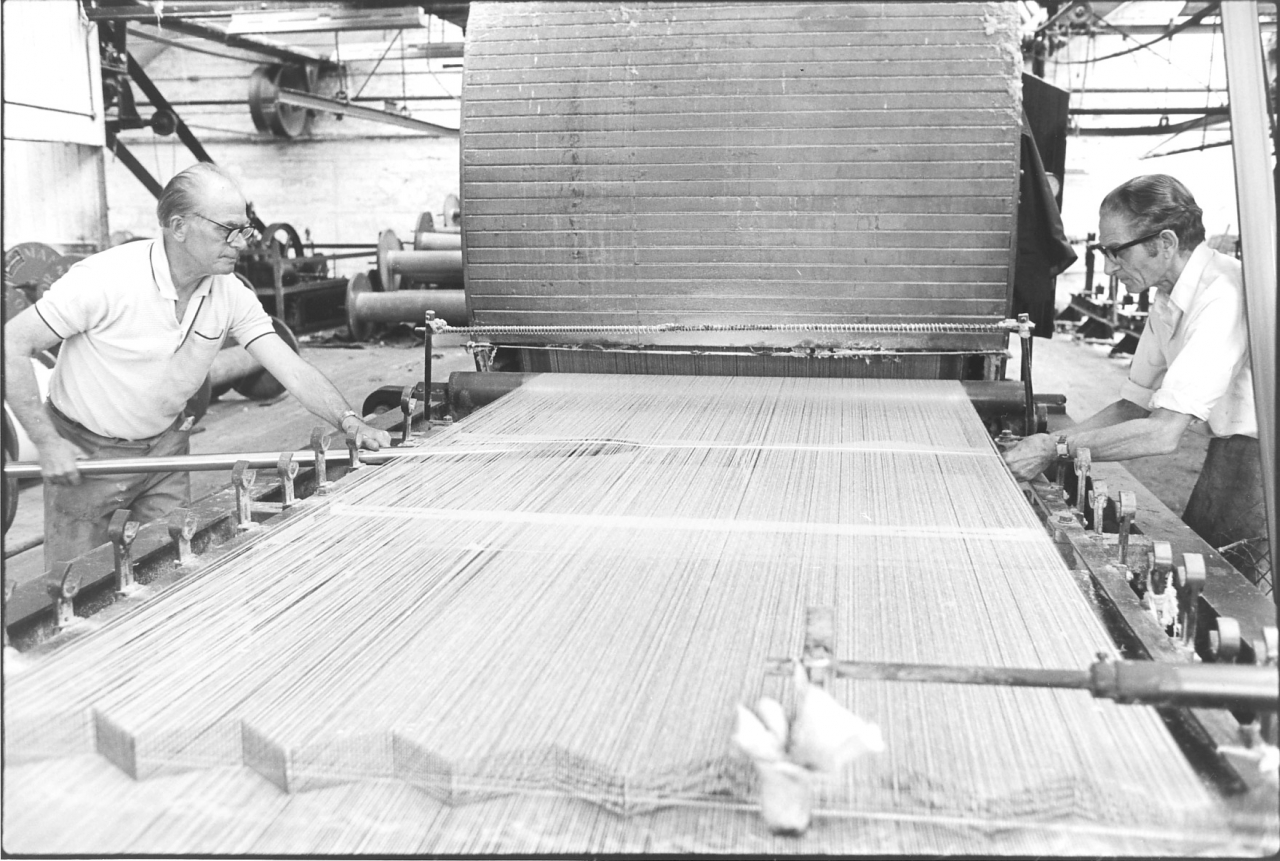
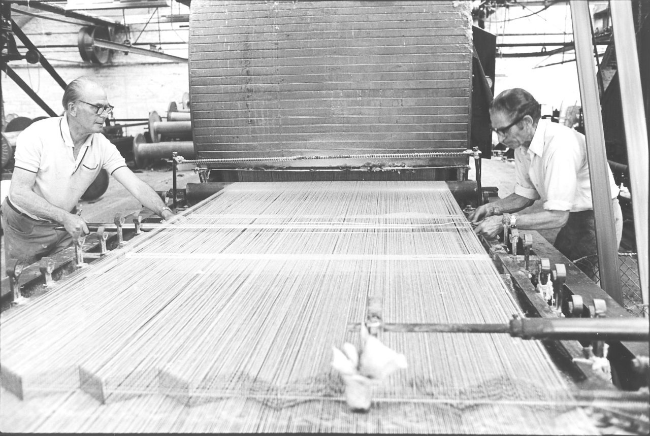
Pictures 61/64. Negative numbers 7719204/05/06/07.
This series of pictures shows Jim and Joe using the splitting bands to guide the polished cast iron splitting rods through the sheet. These rods are lodged in the cast iron housings on the side of the frame and as the sheet passes them they separate one set of threads from the rest. This process is repeated for every splitting band that was inserted on the creel. The effect is that by the time the sheet has passed all those rods every thread in the sheet has been separated from all the other threads.
Pictures number 65/67. Negative numbers 7719238/7719330/7719342.
The tape is still running to waste. In these three pictures Joe is making his final adjustments to the distribution of the threads in the comb. In some mills the individual threads were counted into the dents or gaps in the comb but Joe always did it by eye. When he is satisfied that all these threads are correct he’ll flick the cut marker down so that it marks the sheet. He then sets the cut clock and cuts the waste roller out and replaces it with the first weaver’s beam. He adjusts the comb to make sure the warp is full right to the flange and makes sure that the press roller under the beam is running right up to the flange. The tape has now started on its production run for this set.
Picture number 68. Negative number 7720938.
This is a picture of the sow box while the tape is running. It shows the steam coming up through the sheet and being dragged away up the trunking, the squeeze roller's plainly to be seen, as are also the threads which are distributed over the top to hold the flannel on to it. Notice that the creel's being used, evidently they wanted some more ends in this. There are six ends being put in at each side, that's an extra twelve ends going into that beam. And you can see how even that sheet is as it runs into the tape. It’s very even and running nicely.
Picture number 69. Negative number 7720937.
This is a closer look at the sow box. You can see the immersion roller forcing the yarn down into the size. The sheet emerges from the size and the excess size is forced out as the sheet passes between the lower copper roller and the flannel covered squeeze roller on top.
Picture number 70. Negative number 7720941.
This is a look through the side of the trunking at the cylinder and the sheet of yarn as it's going over the cylinders with the tape running. Remember that one of the disadvantages of this type of taping machine was that the drums were driven by the actual pull of the yarn going over them which means that some of the elasticity is taken out of the warps and makes it harder to weave.
Picture number 71. Negative number 7720902.
This is a picture of the tape running and the first warp is full. Notice how Joe has narrowed the sheet in to build up the warp and get an extra cut on it. He can see from the cut clock that the last piece mark is about to go in and has just put the tape into slow motion. His hand is just leaving the large upright handle on the end of the flat bar which is the lever which puts the tape into slow motion. It’s worth noting on this picture the chain which you can see at the bottom of the picture, wrapped round the end of the spindle assembly on the end of the beam. The end of this chain is a ring which is on the peg you can see on the end of the shaft nearest to the camera. This shaft is driven by a slipping clutch and drives the weaver’s beam round to drag the sheet through the tape.
Picture number 72. Negative number 772090.
The tape is running slowly, the press rollers have been dropped under the weaver’s beam and Joe is resetting the cut clock for the next warp. The cut clock controls the length of the cut, that is when the cut marker strikes. It also counts the number of cuts on the beam. There appears to be a stick laid across the splitting rods on the tape bed. This is the striking comb which Joe is going to use in the next stage of doffing the warp. He has laid it there so it is handy because all the following operations are done very quickly. Remember the tape is running all the time. The reason the tape isn’t stopped is that if it were there would be a danger of scorching the yarn on the hot drying cylinders. These tend to heat up as the tape is running slow because they are not being cooled by the evaporation of the water in the sized yarn on the drum.
Picture number 73. Negative number 7720901.
This is a picture of Joe reaching for the striking comb ready to insert it in the warp. [Actually he was laying it on the headstock ready for when he needed it]
Picture number 74. Negative number 7720900.
On this picture Joe is checking his empty beam to make sure it is ready to use. He lays the correct length pieces of thrum on it so they are ready when he needs them. The striking comb is still laid ready on the tape.
Picture number 75. Negative number 7720903.
Here Joe is putting his striking comb into the warp as it's moving slowly on to the full weavers beam. This comb is put in to preserve the proper order of the ends in the sheet so that the loomer can get them right in the preparation department.
Picture number 76. Negative number 7720904.
You'll see that Joe has put a piece of wood behind the comb. This is a piece of wood with a slot in it and he is pulling it up with his finger and thumb at each end to make sure it’s fully engaged. This wood traps all the ends in the sheet in their proper order. Notice that as that as the warp quietly turns it has trapped both the comb and the backing piece under the sheet.
Picture number 77. Negative number 7720905.
As the comb quietly winds over the top of the warp Joe ties the comb and the backing wood together at each end with a piece of thrum. [I keep mentioning ‘thrums’. These are short lengths of thread which are used in multiples. The individual treads are not strong but ten or fifteen used together are as strong as string and of course far cheaper.]
Picture number 78. Negative number 7720906.
Joe is tying the comb at this end. You can get an idea of how fast he is working, notice that the comb has only moved about four inches while he is tying both ends.
Picture number 79. Negative number 7720619.
Here Joe is unhooking the chain which has been driving the full warp round. Notice the lever mechanism level with Joe’s head in this picture. Compare its position with the previous picture. You’ll notice that Joe has lifted this lever to the top of its travel before touching the chain. This lever mechanism controls the clutch mechanism in the drive to the beam. By lifting it to this position Joe has broken the drive to the beam. If he hadn’t done this he couldn’t have got the chain off. The warp is now free on the front of the headstock, it is no longer being driven. Once Joe has removed the driving chain there is nothing to prevent him lifting it out.
Picture number 80. Negative number 7720907.
Joe has got the drive chain off, you can see it laid on the floor by his left foot. He has reached behind him for one of the large metal hooks hung on leather straps from the roof and is hooking it round the end of the beam where the chain was attached. I should say that on each end of a weaver’s beam there is a small flange which looks like a pulley. This is used in the loom to accept the braking chains which are tensioned by the loom weights. These put a drag on the warp when it’s in the loom. We’ll see these in use later on when we describe weaving.
Picture number 81. Negative number 7720908.
Joe has got both hooks on the beam and by putting his knees into it and leaning back he lifts the full beam out of the drive sockets that the beam pikes have been resting in on the headstock. As he pulls it back the warp rotates towards the headstock allowing some of the sheet on the tape side of the comb to unwind. Remember that the tape is running slowly all the time.
Picture number 82. Negative number 7720909.
As the tape is slowly running the sheet of yarn droops down and Joe reaches for the pair of scissors that are kept in a leather holster on the right hand side of the headstock just below the setting on lever. He uses these to cut the far half of the warp
I once saw Joe working on the tape and at some point during the day he had an appointment with his bank manager so he was wearing a tie. As he leaned over the headstock while it was running in slow motion his tie dropped into one of the steel rollers. It started tightening round his neck but he reached for the scissors and cut it. If he hadn’t done this and couldn’t have reached the stop motion it would have killed him. He was a bit shaken by this and told me that more than one taper had been killed like this, it was the reason he never wore loose clothing.
Picture number 83. Negative number 7720623.
Joe cuts the other half of the sheet. Thus the full beam is completely detached from the tape and can be ignored while he fits the new, empty beam.
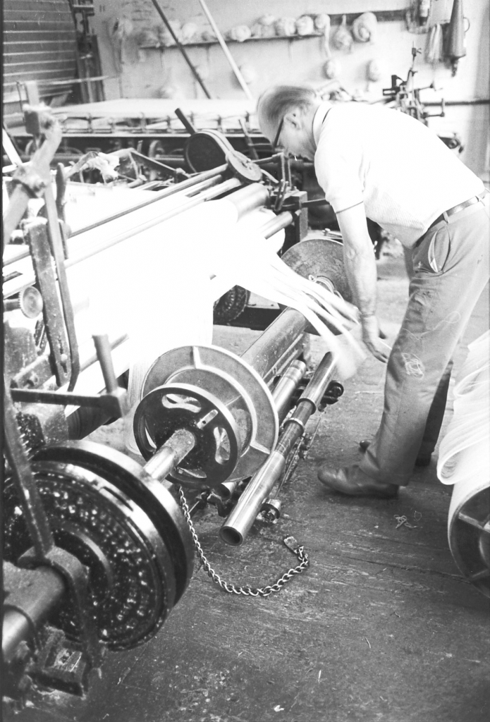
Picture number 84. Negative number 7720911.
Here Joe has lifted the empty beam in and is dropping the free ends of the sheet coming from the tape onto the wooden centre of the beam. He tries to get them reasonably spread on the beam when he does this so as to give the new warp a good start.
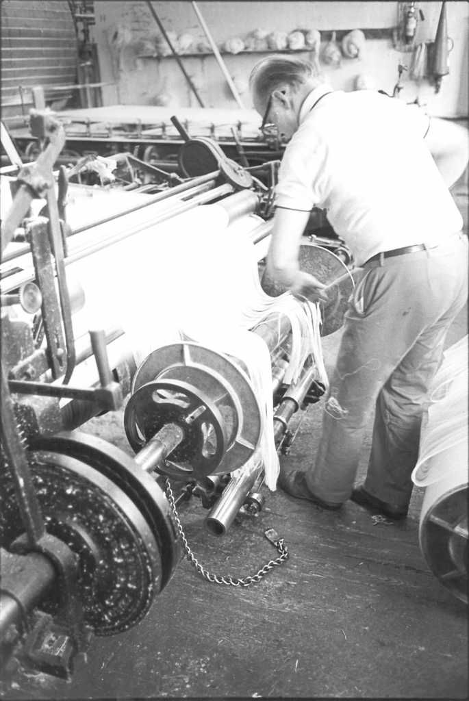
Picture number 85. Negative number 7720912.
When Joe was readying the empty beam on picture 74 he fastened a piece of thrum on it ready for this stage. He is using this band to tie the first foot of the sheet in place on the weaver’s beam.
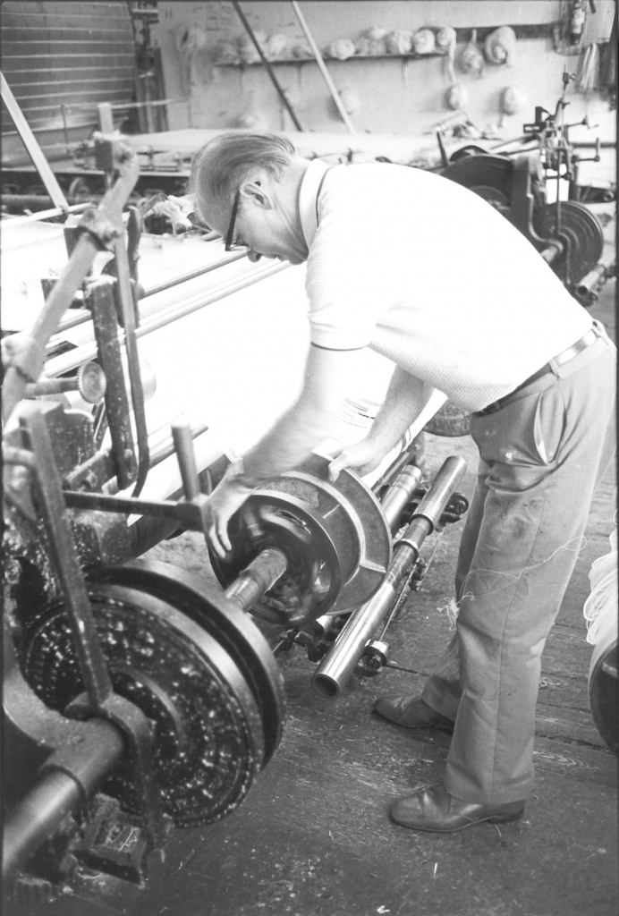
Picture number 86. Negative number 7720913.
In this picture Joe is rotating the weaver’s beam by hand to take up the slack in the sheet. Notice that the drive chain has vanished from the floor. Joe has re-attached it to the beam and when he has taken the slack up he will hook the ring in the end of the chain onto the peg on the flange which will be driven by the clutch. Notice that the lever mechanism controlling the clutch is still at the top, in the disengaged condition.
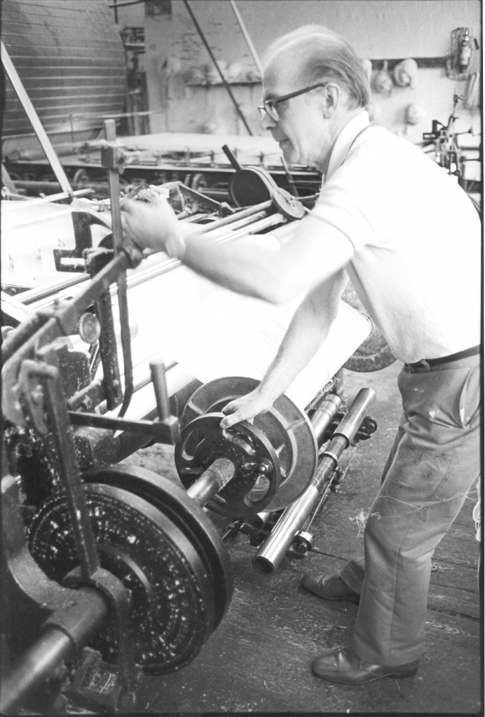
Picture number 87. Negative number 7720914.
Joe has now taken up the slack in the sheet, attached the drive chain and he is dropping the control lever to re-engage the clutch. The weaver’s warp is now firmly attached to the drive and is being driven in slow motion by the tape. His next move and one that isn’t in the picture, is to increase the speed of the tape slightly.
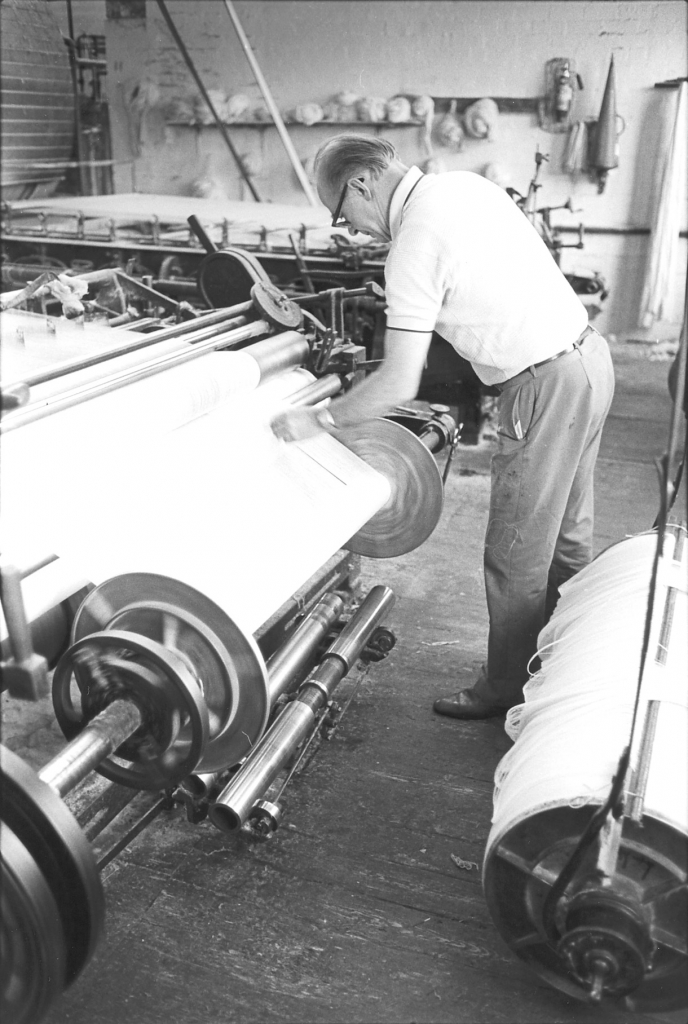
Picture number 88. Negative number 7720917.
Joe is almost ready to put the tape back to full speed but he has noticed a small fault, perhaps a crossed thread and he is adjusting that before he goes any further. You can see by the blur in the clutch shaft flange that the tape is moving faster and at the far end of the beam you can see the scissors hung in a leather holster ready for use.
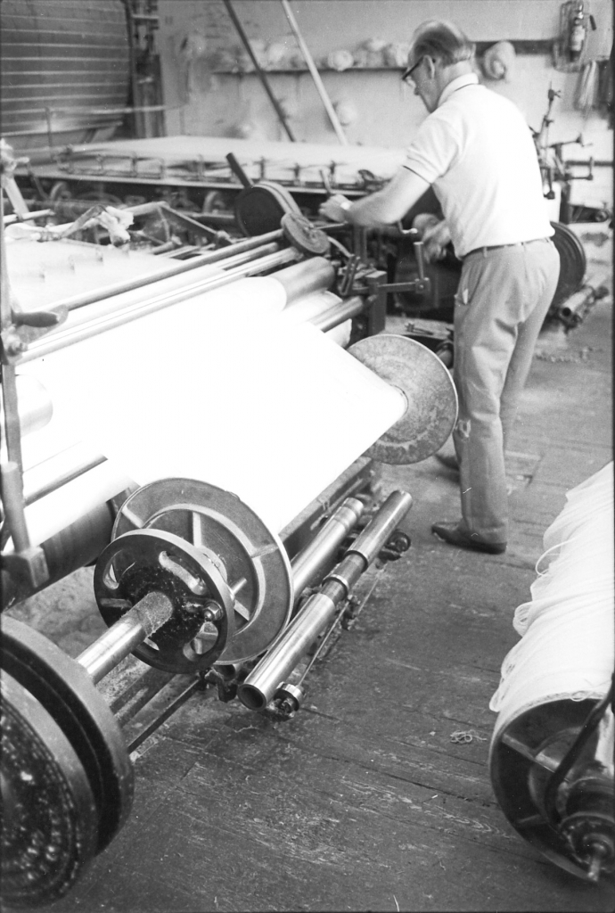
Picture number 89. Negative number 7720915.
In this picture Joe has evidently decided all is well. He has adjusted the position and width of the sheet and he is ready to put the tape back on to full speed.
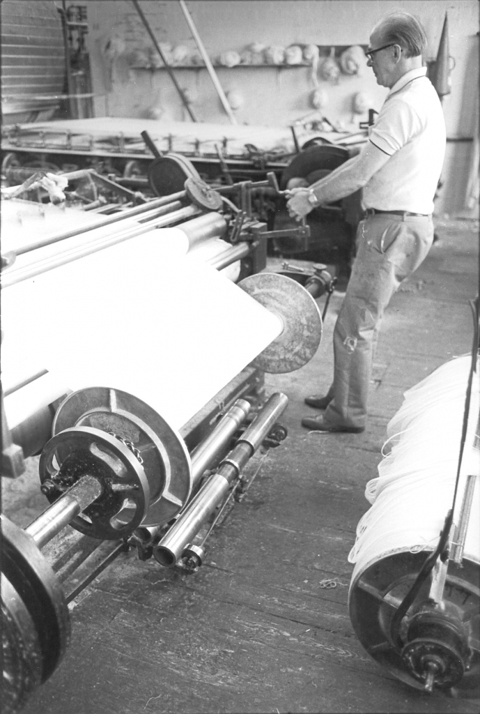
Picture number 90. negative number 7720916.
Here you can see Joe leaning back as he pulls the speed rod back to put the tape back on to full speed. He does this quite gently as he is putting a lot of strain on both the tape machine and the warp sheet. When he does this the belt squeals on the pulley as the weight of the drive comes on it. It takes a lot of power to accelerate the tape to full speed.
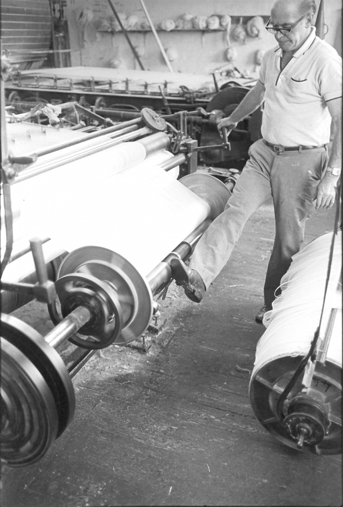
Picture number 91. Negative number 7720918.
In this picture you can see that Joe has lifted the press up underneath the warp and he is just pushing the front rollers out with his foot so that they run up against the flange at each side and keep the threads all nicely pressed down and even so they wind on evenly.
Picture number 92. Negative number 7720919.
This is Joe’s final check on the running of the sheet on to the new warp. As I mentioned earlier, the process of doffing a full warp means that the tape is in slow motion long enough to raise the temperature of the cylinders. Once the tape is running at full speed these factors soon even out again and the temperature of the cylinders drops to normal levels. This is a very common sight to see on an old tape with no sophisticated temperature control mechanisms on it. The only check that is applied is the taper’s skill. What Joe is doing here is letting a few threads run over his fingers as he puts slight tension on them. He is checking elasticity, quality of sizing and moisture content and all this by the feel of his hand. This level of skill was only gained by years of experience and is the reason why I believe that a modern taper would be lost on this machine until he had got a lot of experience. Jim Pollard told me that the quality of taping at Bancroft had never been a problem.
Picture number 93. Negative number 7720940.
This is a close-up of the mechanism at the end of the headstock which controls the clutch which drives the weaver’s warp. I never really understood this completely. I never had time to examine it closely and never saw it stripped down. It is a very sophisticated mechanism in that it puts enough drive through to the weaver’s beam to keep the tension between it and the drive roller in the headstock constant no matter what the effective diameter of the weaver’s beam is. This of course alters constantly as the warp winds on to it. Just below this mechanism you can see a cotton covered roller, this is the main drag roller which is actually pulling the sheet through the tape.
Picture number 94. Negative number 7720920.
As the tape is running Joe is making one or two adjustments to the number of threads passing through the comb. This is the position he was in when he got his tie caught in the drag roller.
Picture number 95. Negative number 7720939.
This is a picture of the warp running normally. This is a 56” warp and everything is running well. Note the arrangement of levers on the press roller under the beam. This is a clever little mechanism which exerts a constant pressure on the movable sections of the roller making sure that it always runs up to the flange. We saw Joe pushing the rollers out with his foot earlier, this is because the automatic mechanism is very slow and Joe wanted to make sure the rollers started up against the flange. You can clearly see the bosses on each end of the warp and the driving chain on the left hand boss. There is also a clear view of the cotton covered drag roller and the steel rollers which keep the sheet in intimate contact with it.
Picture number 96. Negative number 7720921.
Joe now turns his attention to the full warp which is still hung in the hooks from the beam above. He has slipped a card under the sheet on the warp which identifies the number of ends, the count of the yarn and any details he has of quality and eventual use.

Picture number 97/99. Negative numbers 7720922/7720637/7720634.
These three pictures show Joe tidying up the finished warp, tying the comb down and making sure that even if this warp sits around waiting to be loomed for a few weeks it will not have deteriorated.
Picture number 101. Negative number 7720825.
Joe is heading off up the side of the tape with the finished beam on his trolley.
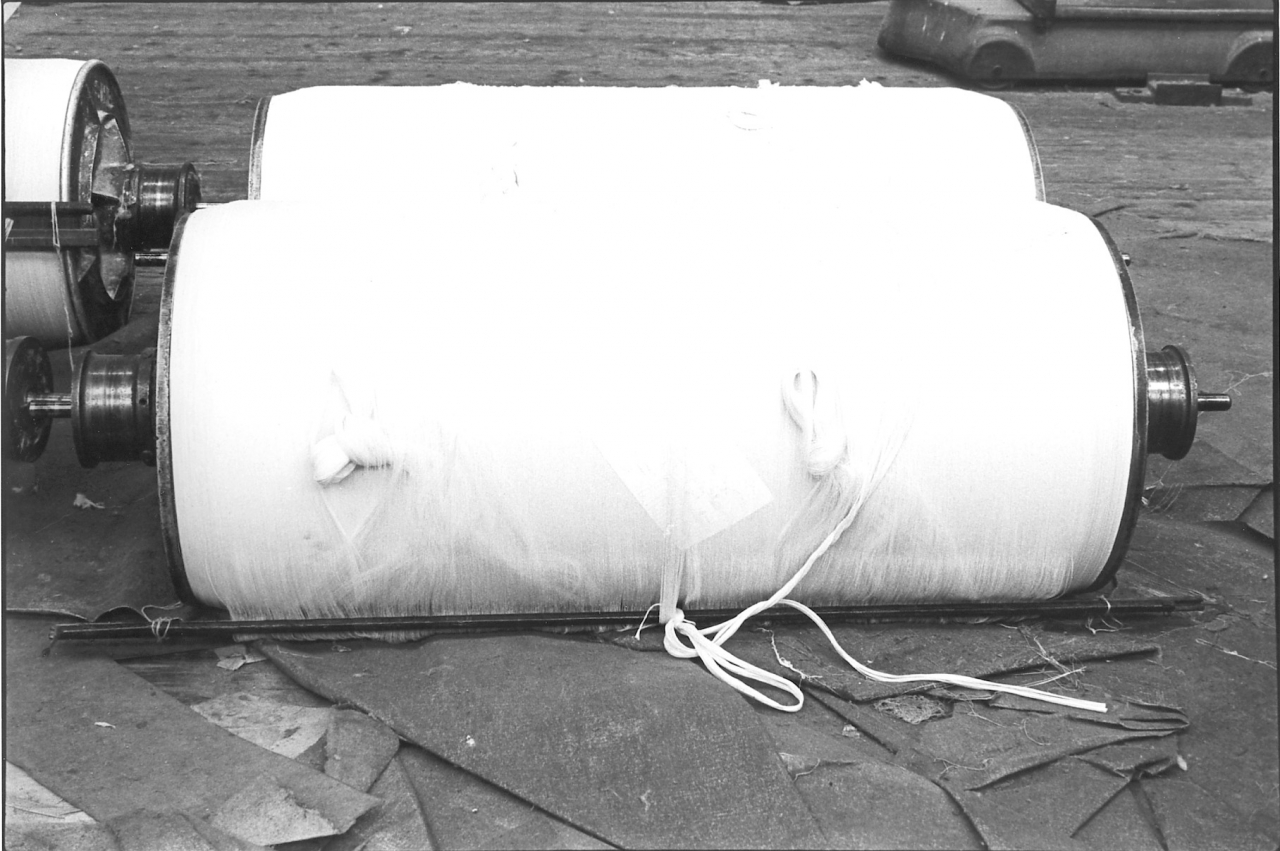
Picture number 102. negative number 7718209A.
The finished warp lay outside the preparation department waiting to be taken in and loomed. Notice the warp card trapped under the sheet of yarn.
Basically, that is the process of taping a warp. Now of course there is a lot more to it than this. Things like mixing size and the different little tricks of the trade there are to make sure that one lot of size is of equal consistency with another. Obviously I can't tell you about these things because I don't know about them. It's only possible to do so much in a certain length of time. For more information go to the description of these pictures given by Horace Thornton in the 79/AD series. Howard and Bullough of Accrington were the main manufacturers of this type of taping machine. There was another manufacturer, Butterworth and Dickinson of Burnley who made an almost identical machine.
The taper spent a lot of time just sitting down once a production run was got going. As long as there were no faults it was possible for a taper to take it very easy and many a time you'd go up there and find the tape running away and Joe dozing off quietly. It might have been the wrong way to do the job but I remember a fellow once telling me that if you have got two blokes doing a job, and one is always rushing round and the other one seems to be asleep half the time but they are both doing the job, he said if you are going to sack one, sack the one that's rushing round because the other fellow's doing the better job. I can sympathize with that point of view, I can see the sense in it. You'd never see Joe rushing but he was a very, very good taper. He might not have been the best man in the world with a brush and a shovel but by God he was a good taper. There's no doubt about it as you'll hear when you listen to Jim. You listen to Jim talking about what was going on. You can have the best warps in the world, you can have the best machinery, you can have the best looms and the best weavers but if your taping's no good your weaving's no good. Everybody in the mill depended on everybody else. Everybody else in the mill could work their fingers to the bone but if Joe wasn't doing a good job they were wasting their time. It’s as simple as that. This was common of every job in the mill, everybody depended upon everybody else. It’s a shame really that that sort of ethos is vanishing now. People don’t want to be responsible. I often think that's one of the reasons why steam engines went out. Nobody in their right mind wanted one man controlling the production of an entire factory because in most cases if the engine driver didn't turn up the engine didn't start. This was certainly what happened at Bancroft. If I didn't get up in the morning, if I was late, they didn't start, because nobody else knew how to start the engine.
In point of fact there were odd occasions when I did sleep in. The nearest I ever got to disaster was one morning when I woke up at ten to eight. I only lived about 300 yard from the mill. I woke up at ten to eight, dashed across to the mill and actually had the engine going by one minute past eight. The fact that I don’t think I had a single button done up and my boots were unlaced didn't matter, the engine was running. I always used to leave things in a condition where we had the least possible work to do in the morning to get going but that’s another story. We'll perhaps get on to some of the little anecdotes about things that could go wrong and things that did go wrong later in this series of tapes. For the moment we'll try and confine ourselves to facts. I don’t intend to start on the next series of pictures on this tape because this is actually a good place to finish because that is the end of the series of pictures on taping. So I shall finish this tape now and start a fresh subject on the next tape.
SCG/20 September 2003
6,724 words.
LANCASHIRE TEXTILE PROJECT
TAPE 78/AI/09 (Side two)
THIS TAPE HAS BEEN RECORDED ON MAY 1ST 1979 AT 13 AVON DRIVE BARNOLDSWICK. THE INFORMANT IS STANLEY GRAHAM WHO WAS THE ENGINEER AT BANCROFT MILL AND WHO HAS BEEN THE INTERVIEWER ON MOST OF THE TAPES..
I shall carry on now with the description of the pictures in the looming folio. This is the series of pictures which deal specifically with Jim Pollard at work at his looming frame. The pictures are numbered from 1 as they were originally presented as a separate folio.

Bancroft folio, looming picture number 1. Negative number 7717520.
This is a picture of James Pollard. At the time of the mill finishing he was 62 and had been in cotton all his life. Jim made his own series of tapes, the 78/AA series and for a fuller story of Jim, obviously, I refer you to that set of transcripts.
The first thing I should do is declare an interest. It will become obvious I think that having worked closely with Jim for six years and after many discussions apart from the tapes we did, I have nothing but admiration for the depth of his knowledge about the workings of Bancroft and his abilities as a weaving manager and loomer. Jim is the sort of man upon which the fortunes of the big cotton manufacturers were founded. He was conscientious in the extreme, honest as the day is long and reared in the old fashioned way where a hard day's work wasn’t considered to be anything to he ashamed of. Rather something to be proud about. Jim survives as something of an anachronism nowadays, somebody who really enjoyed his job, did the very best at it he could and in consequence slept soundly at night. I have a lot of respect for Jim and for the sort of work he did. He was tremendously skilled, inventive and also a master craftsman. So, we'll go through the set of pictures I did of him working.
The first thing to do is specify briefly what looming is. Looming should not be confused with twisting or re-using a set of healds and reeds that have been cut out of a finished warp and re-knotted on the Barber Coleman knotting machine. Both twisting and the Barber Coleman are ways of attaching a set of healds and reeds that have already been loomed on to a new warp by knotting all the individual ends to each other.
Looming is starting from scratch by selecting the correct heald and reed and drawing the ends through in such a way as to produce the cloth that is required. It demands an intimate knowledge of cloth construction and even more important, knowledge of how the warp will behave in the loom. There are no hard and fast rules for producing a certain cloth to the correct width and pattern of weave. Cloth contraction in the loom is a product of many factors and these are discussed in great depth in the tapes I did with Jim. Suffice it to say that the profit made on a type of cloth was decided largely by the skill Jim exercised in specifying yarns, instructing the tapers on how he wanted it processing and his own skill at the looming frame. Like many other jobs in the mill, there is more to this craft than meets the eye.
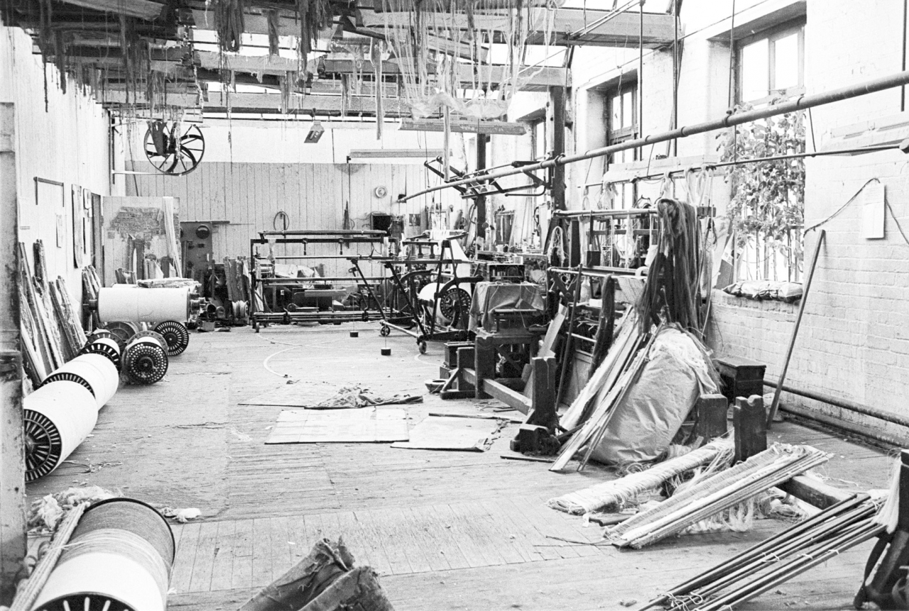
Picture number 2. Negative number 7717935.
This is an overall shot of the north end of the twisting room, that is the end which butts up to the cart-race where the teagle hoist is and beyond that the tape room. In the top left-hand corner is the pulley which takes the drive from the cross belt, across to the shaft which I described over the donkey engine, and forward into the tape room. At one time that belt also used to drive the teagle hoist. In the top left-hand corner of this room you can just see the vague suggestion of a black shape and what looks as if it might he an electric meter. That is an old DC dynamo which was driven of the shafting and provided DC current for the Barber Coleman knotting machines. I say knotting machines because in the days when this mill was full up with 1120 looms there were two knotting machines working. Now we only have one which can be seen on the far right with a weaver’s beam mounted in it.
Really, there is rather a large gap in our description of Bancroft. This is the fact that I have no series of pictures of the Barber Coleman operator working on his machine. There is a very simple reason for this, the man hated my guts! My experience is that there was no point in doing the pictures if you hadn’t got the confidence of and a relationship with the person who was doing the job. It’s a sad thing but it just so happened that the man, Jim Greenwood, who ran the Barber Coleman machine had neither friendship, confidence or any fellow feeling whatsoever towards me and so those pictures never got done which is a shame. But there again, we did get the rest of it, but that's the reason why there are no pictures of the Barber Coleman machine being used. There is a story behind this animosity which tells us some interesting things about the way the internal organisation of the mill worked and gives some indication of how serious mechanical faults could arise.
The first bone of contention might have been that Jim Greenwood had a candidate for the engineer’s job and I pipped him at the post. I was told this years after the mill closed but have no idea whether there is any truth in it. If true, it would explain a lot. There was another matter as well. As I have already said, we had an alternator in the engine house and made our own electricity to mains standard. This was 50 cycles, 440 volts three phase current. By taking one phase and neutral this gave single phase at 250 volts. However, for many years it had been recognised that our current wasn’t up to mains standard. The reason why I knew this was that when it was the day for making the wages up I always had to switch the office circuit on to mains power because the old electronic calculator they used in the office wouldn’t run off mill power. Sidney Nutter said the decimal point jumped all over the place.
I was always getting complaints from Jim Greenwood about the fact that he wasn’t getting enough power for his machine. The Barber Coleman machine was an American machine and ran on DC power at I think 115 volts. This was rectified from the mill electricity and supplied to the machine. I am not sure whether it was a mercury rectifier or a rotary converter. These complaints from Jim Greenwood got more and more vitriolic and he accused me of being frightened of the engine and not running fast enough! Apart from his lack of knowledge, speeding it up wouldn’t have cured the problem, the fact was that the cycles were perfect, the electric clock in the engine house kept perfect time.
In the end this constant abuse led to a stand-up row and I determined that I would cure the problem.
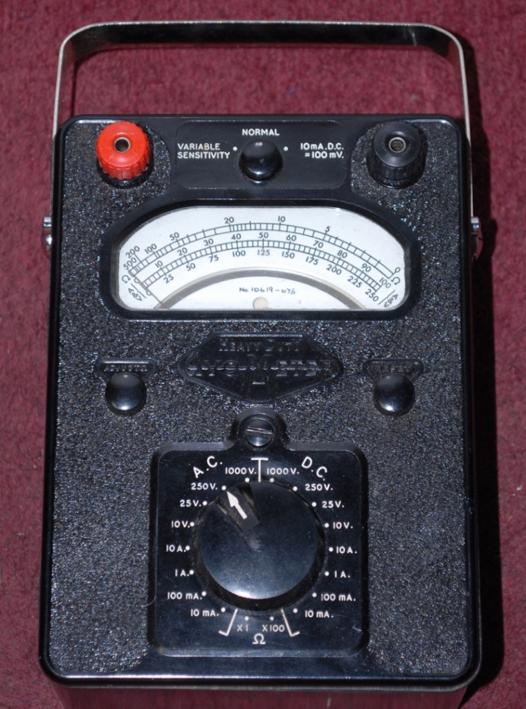
I went out and bought an Avo heavy duty meter for £85, two week’s wages, and took readings of everything. I got a severe shock. The voltmeter on the engine distribution board had been altered at some time so that it read the correct voltage even though it was actually wrong. The root problem was that the resistances in the circuit which carried power to the exciter on the alternator had deteriorated over the years and it wasn’t possible to get enough current to the exciter to attain the full 440 volts. We were actually making 400 volts three phase and about 215 volts I think on single phase. I had a word with the office, got the sparks in and we replaced the resistances in the exciter circuit. This gave an instant cure. The variable resistance used for fine adjustment of the voltage could be run in the mid position and I was making 440 volts on three phase. Single phase went up to just short of 250 volts.
The first consequence of this improvement was that the next time I switched the shed light on approximately 20% of the bulbs in the shed blew. As my father used to say, there is a providence that looks after drunken men and idiots and I had bought a lot of Edison screw bulbs from a fairground proprietor who had converted to bayonet fittings so the bulbs in the shed were no problem. Shortly after I made the adjustment Jim came to see me. He said that Jim Greenwood was not a happy man. His knotting machine was running approximately 50% faster than it had before and this had shown up all the faults in maintenance which the operators had been getting away with for years. I shame to say I took great pleasure in going up and telling the man that he had asked for more juice and now he’d got it. I had cured a twenty year old fault and the ball was in his court. He never spoke to me again all the time I worked there. Sidney Nutter was pleased because his calculator worked perfectly. He told me to ignore Jim Greenwood. I did and so this is the reason there are no pictures of the knotting machine. The weavers also gave me a vote of thanks because the shed lights were a lot brighter. Big improvement all round and all because some small and inexpensive fixed resistances needed replacing. I think the job only cost about £15 and I wondered how much money had been wasted over the years.
Now, looking at this overall picture the Barber Coleman machine occupies the top right-hand corner with its associated two frames, two back frames, and the actual knotting machines and beyond that the preparation frame. Just this side of that is a looming frame which has all sorts of stuff piled round it and stocks in front for putting a warp on, you can see which never actually got used. This was a mechanised looming frame, supposed to be an automatic looming frame, but in point of fact it was never used as such. It probably had been in the old days but they were never really a success. I didn’t know it at the time but Jim bought the frame [he always used] out of his own pocket and when he finished he took it home and put it in his garage! Incidentally, in the window bottom behind that can be seen a phenomenon which was common at Bancroft during the summer. Tomato plants growing in plastic bags full of soil on window cills. The atmosphere in Bancroft seemed to be conducive to growing tomatoes and there's been some very fine crops. In point of fact these belong to Jim Greenwood the fellow who ran the Barber Coleman and I don't think Jim lavished any more attention on his plants than he did on me and they were rather spindly things and never really cropped that year. [I have a funny feeling the man was actually called Fred Greenwood but there is no way of telling now in 2013!]
So there we are. On the right another pair of stocks, this was where there used to be another knotting frame which was not used because there wasn't the need for it. The one that Jim uses is further back to the right. It's not included in this picture but we'll be seeing plenty of that in a minute or two. Some other interesting things in there, warps on the floor ready for being processed. Notice every now and again bags on the floor, pieces of felt and things like that, those are just to let the warps stand on. It's kinder to them than the boards and saves them picking up muck and splinters. In front of the camera you’ll see a stretch of new boarding going across the floor, which looks to have been terribly attacked at one point. This is some new boarding which was put in on the instructions of the factory inspector because the old boards had got so worn that it was dangerous. The fact that it's all scarred and chewed up is due to the fact that Jim used to cut his reeds there. In fact if you look very carefully at [the] healds and reeds lay on the disused stocks on the right, in between them you'll see two handles sticking out, those are actually his hammer and his chisel with which he cut down reeds to make them the right size for his warps that he was drawing.
I should explain that apart from one or two occasional circumstances, Jim, or rather Bancroft, never bought any healds or reeds for about 15 or 20 years. What Jim used to do was when cotton mills closed down he got people to give him their old healds and reeds and adapted them to use at Bancroft. He saved the firm thousands of pounds. In the rafters you'll see hung up sets of healds and reeds out of warps that have come out of the mill. If you have a warp in the shed and you are going to do exactly the same sort again, that warp has already been drawn through those healds and reeds in the right order. All you do is set them up in the Barber Coleman and the machine works its way across, knots all the old ends on to the new ends, and then all that you need to do is slide the healds and reeds over the knots and you’ve got a warp that's ready to go into the mill without re-looming it.
This is a great labour saver when you have got a shed that's working on standard sorts or on a few sorts. In other words with continuity of production. As one sort comes out of the loom it's replaced by the same sort. Under ideal circumstances you'd have one mill weaving one sort. Unfortunately Bancroft was struggling all the time for orders and we used to be in the position, well at one time we had three hundred odd looms working on twenty eight different sorts. This meant that almost every warp that went back into a loom was a different sort than the one that came out. As a consequence this meant that very often there was very little work for the Barber Coleman machine. We were working on new sorts nearly all the time, fighting for orders, getting different sorts, and having to re-loom them all, because obviously we didn't have sets of healds and reeds ready to be processed on the Barber Coleman. They had to be re-drawn from scratch and this was down to Jim and his knotting frame. We’ll look at a set of pictures now of Jim setting up a warp in the frame and looming it.
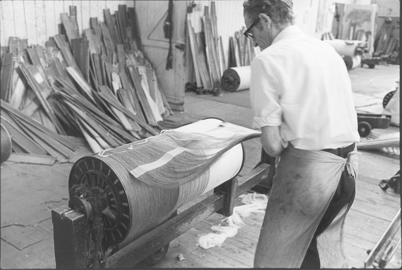
Pictures number 3/4. Negative numbers 7719032/34.
This is a picture of Jim stood in front of the stocks, or rather stood in between the stocks and the looming frame. Look at this in conjunction with picture number 4. Actually, this looming frame was designed so that the warp could be hung up in the two big hooks that you can see at the top on the frame. We never used to use it like that, we put the warp in the wooden stock and led the sheet up over the rod that Jim has placed in the hooks. It made a lot of work lifting that warp right the way up there and then lifting it down. It was easier to do it the way that Jim does it. You can rest assured that everything that Jim does with this warp is done in the easiest way possible. [There’s an old saying about this: ‘Give a lazy man a job and he’ll find the easiest way to do it.’ Nothing to do with laziness in this case, just the search for efficiency. It should have said ‘busy’ not lazy.]
There is something I should point out about this warp which is that we didn't tape it at Bancroft. It's one of the very few that weren’t taped by us. We used to refer to it as a polyzone warp, it was a mixture of worsted, the black end nearest to us or the very dark grey end was pure worsted. Then the next was half worsted and half polyester which was a very coarse yarn, and the other end was all polyester. It was a very hard sized yarn and wouldn't have gone through the Barber Coleman. It couldn't have dealt with it, not the machine that we had anyway. These warps were actually a good example of what happens when a mill is failing. They were not our preferred sorts but we had to take whatever we could get to keep the looms running. We were weaving these on commission for a Bradford firm. This meant that they were sub-contracted to us by the mill that had got the order and we got less profit out of them. The cloth was a lining cloth for men’s suits and the three grades on one cloth was something to do with the way the cloth was used. Funnily enough, due to the way the Uniform List of Prices for weaving was drawn up, these warps were the weaver’s friend because they got a good piece rate for weaving them. So all these were to draw through afresh each time. This is the warp that Jim's working on and it's the warp that is also described when Ernie Roberts, the tackler, is gaiting a loom later.
Jim has just taken this warp which hasn’t got a striking comb in it because we haven't taped it. It came with a piece of sticky tape across as you can see to keep it in some sort of order. Jim is starting right from the beginning with this warp but basically, apart from having to put his own striking comb in, the process is exactly the same as it would have been if he had been dealing with a warp that had been taped at Bancroft. The first thing he is doing in picture number 3, he's got the warp in the stocks and he is straightening all the ends out on it, getting the packing off and getting it into some sort of order. In picture number 4 he's draped the sheet over the frame and he is weighing it up to find out what he has got and getting things into some sort of logical order.
Pictures number 5/6. Negative numbers 7719036/38.
When he has got it on the frame and temporarily held in a clamp he puts a rod on to weight it and get a bit of tension. Then he puts his striking comb in well back into the warp so he has the best chance of picking the ends up in order. He’s spread the ends out over the slotted wooden back of the comb and has got them as straight as he can. He draws the comb down through the sheet on picture 6 and finishes up with his warp held in the striking comb as even as he can get it and ready for gaiting into the looming frame.
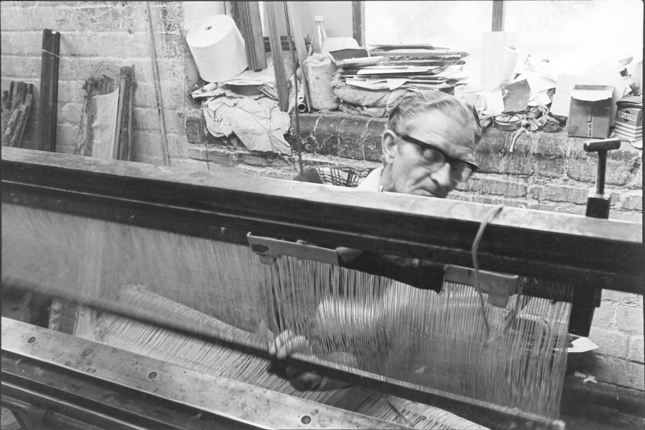
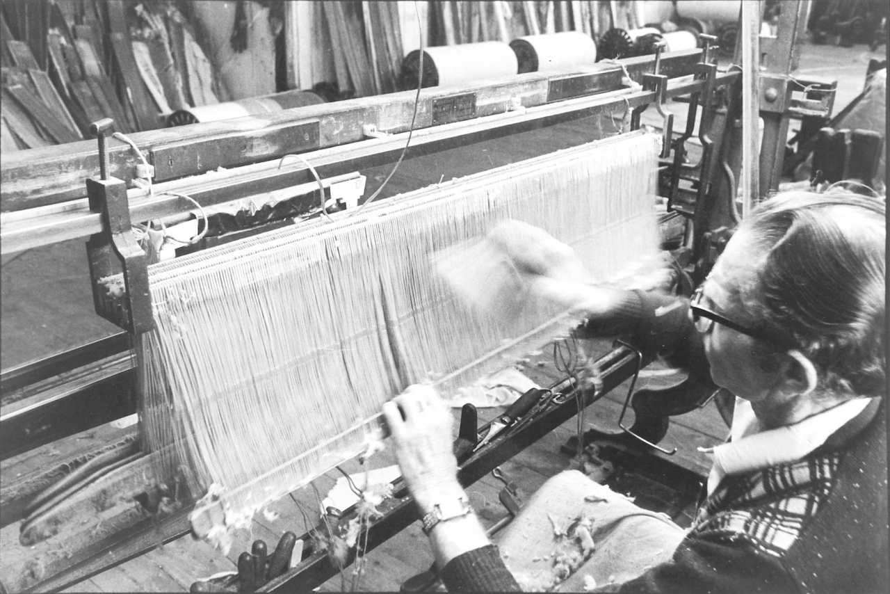
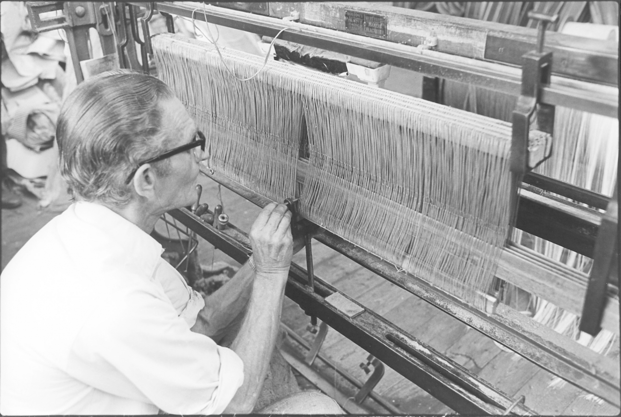
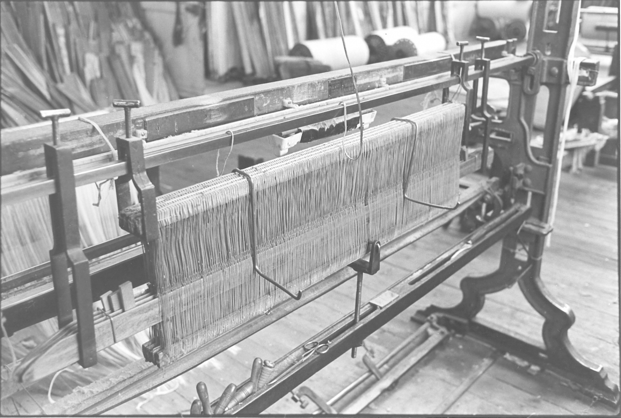
Picture numbers 7/12. Negative numbers 7717936/37, 7717619, 7719833/35/39.
Picture number 7 is a picture of what would be the first stage in one of our own warps because the striking comb would already be in. Forget the warp for the moment, what we are looking at now is setting the healds and reed up in the looming frame ready for gaiting up. This is the stage where Jim makes his first independent decisions based on experience. He chooses his healds and reeds to suit the finished cloth he wants to produce. He has first to select good healds with no broken or damaged eyes and a reed with the correct number of dents [spaces] per inch to suit the cloth. This is where he may have to cut down second-hand healds and reeds to size. He will use a pair of fine nosed pliers to straighten out and bent wires in the reed.
The first stage is to set the healds up in the frame. The number of healds depends on the cloth construction he has to achieve. A plain cloth will have two healds, a twill will have four. There are many combinations and remember that the ends have to be drawn through the right heald in the right order. It isn’t just a matter of bringing all the ends through all the heald eyes at the same time.
O pictures 7 and 8 Jim is installing the healds in the frame. There are four for this cloth. He picks out the larger lumps of dawn and dirt and examines all the eyes to make sure they are serviceable. Notice the clutter on the window cill behind him. This is where Jim keeps just about everything he needs to do his job. The funny thing is that an ‘efficiency expert’ would throw a blue fit at this evidence of disorganisation but as we shall see, he might be wrong in Jim’s case. Look at the corner there to the left of Jim. The whitewash has been rubbed off over the years by people leaning on the wall to talk to Jim and Jim leaning on the wall and having a warm over the pipes.
In picture 9 Jim has got his healds sorted to his satisfaction and gives them a good brushing to get all the dust and dawn off them. Notice on the bottom bar Jim’s collection of reed hooks and slay knives together with other small tools. Look how his fent or brat on his lap is covered with dirt which he's brushed out of the healds. He's already got his rods through three of the healds that are hung there. In picture 10 you’ll see that he has got rods through all four of them. In picture 10 he is putting the clip on at the bottom which puts the tension on the healds when he screws it up at the bottom. This holds the assembly tight and steady so that he can work on it. It tends to hold all the eyes in the right position and level. One or two odds and sods laid about there. There's that square object lay on the frame just in front of his right arm as he's pushing that pin through, that is actually a reed stone which is a very fine piece of abrasive stone which is used for polishing the face of the reed if it's been caught with a shuttle and damaged or something like that.
In picture number 11 we see the healds all cleaned and set up and properly tensioned in the frame. Notice that the rods have also been tensioned upwards and are bearing against the bottom of the eyes, in other words they are holding those eyes level, straight and level. Notice that wedges have been put in between the rods and a clip put over the four rods to restrain them against the pressure from the wedges so that the four rods are held at an even space apart. All this helps him to get his hook through quickly and accurately and make a good job when he is looming. The lamp that's hung up in the frame, at the time this picture was taken it hadn't got a strip-light in it. We were waiting for one coming but he used to have that light there and it used to slide from one side to the other and he could put light just exactly where he wanted it. You'll notice in the frame the odds and sods laid about, a knife nearly worn out but very sharp, pair of scissors, the reed stone, and then various polished wooden handles stuck up on the left hand-side. These were all things that he used each day while he was doing his job.
On picture number 12 we see that Jim has laid the reed on the two hooks which hang over the top of the healds. He’s got his tape on there and he is marking out on his reed. These marks give him distances or points on the reed where certain elements of the warp should be when they are drawn in. He'll split those marks again afterwards and they are there to give him an even count all the way down so that he can tell exactly what he's doing when he starts drawing. Notice that his slay knife is already hooked into the reed at this end, you'll just see the tip of it hung through the reed. More of that in a minute or two when we come to it. This is actually a very important part of the operation and is what we call ‘casting out’ his looming marks. This is actually where he sets the warp up for the weaver and it's a very skilled job. In this case he is dealing with a cloth of 36” finished width and so he allows it 37 ¾ “ in the reed to allow for shrinkage due to contraction caused by the weft when it is weaving in the loom. This allowance varies with the weight of twist, the density of the cloth and many other factors. The only sure guide is years of experience.
If you notice on this reed there are three black marks just about nine inches to the left of Jim's left hand. These are brass dents, each strip of polished steel in that reed is called a reed wire and the space between is a dent. Those are brass ones and they're so positioned that by looking at them you can tell what size that reed is. There'll be four spaces between the first two, or rather four dents in between the first two brass wires and two dents in between the next. That's 42 dents to the inch which is the size of that reed. It saves counting how many dents there are in an inch. This is where Jim governs the cloth construction by the number of healds, the way he laces them up, the size of the reed, the width, any combination can be done here. In actual fact these are what are known as simple cloths that we are doing here with four staves. It is possible with a Jacquard to have 30 or 40 staves to a cloth. This makes looming far more difficult of course but Jim’s is difficult enough here. The only difference is that with a Jacquard with a lot more staves in. The staves in a heald are the flat pieces of wood that go through each side of the heald. There are four at the top and four at the bottom in this set. The more staves you have in, the more complicated things get. But actually the principle is exactly the same.
Picture number 13. Negative number 7719840.
In this picture Jim has returned to the warp. He has got it into position and he is hanging his comb up, with the lease of the warp trapped in it, just on that top rail with two pieces of string.
Picture number 14. Negative number 7719842.
Here Jim has put a bar under the sheet of warp and lifted it up and put it in the two hooks at the top where originally the beam itself was supposed to hang. Notice that his comb is still tied on to the back of the frame with the lease of the warp running through it.
Picture number 15. Negative number 7719801.
The next thing he does is pass all those ends down through the large clamp at the bottom of the looming frame.
Picture number 16. Negative number 7719802.
He has got all his ends as evenly tensioned as possible and has temporarily clamped the tail of the warp in the frame. What he is aiming for here is to get the sheet in exactly the right position and as even as possible against the wooden beam above the healds and reeds.
Picture number 17. Negative number 7719804.
Jim is satisfied with the orientation of the top of the sheet so he clamps a piece of wood across it to hold it in place.
Picture number 18. Negative number 7719806.
Now the top of the sheet is positioned and clamped Jim opens the bottom clamp and passes the comb down through it. It’s not easy to see but notice at this point that the bottom clamp is lined with felt. This allows it to hold the sheet firmly but allows Jim to draw the ends up through it and through the healds.
[In the original folio 17 and 18 are the wrong way round. On 17 the clamp is being fitted, on 18 it is in place. Apologies for that if you are looking at the originals.]
Picture number 19. Negative number 7719808.
Jim has got his sheet straight in the bottom clamp and has tightened it up by pressing it in with his left hand while with his right he is fitting one of the ‘G’ cramps which push the clamp dead tight up against the warp sheet. Notice that a small mechanism has put in an appearance on the end of the broad cast iron track nearest to the camera. This is the traveller which is operated by a pedal on the floor which actuates a bar running across the back of the traveller bed. This little mechanism saves a wage because instead of having a ‘reacher in’ on the back of the frame. That is a labourer sat on a buffet who’s job was to select the ends and hold them in position for the loomers reed hook. The traveller does this automatically each time the pedal is pressed. The bed on which it runs is pivoted so that it can be moved back from the warp sheet while the comb is threaded through.
Picture number 20. Negative number 7719319.
Jim has moved the traveller bed up to the warp, notice how it has pushed it in towards the healds. Jim is tightening the clamp at the far end which holds the bed in place and he will do the same at this end as well.
Picture number 21. negative number 7719320.
Jim is making his last checks on the tightness of the ‘G’ cramps holding the bottom clamp on the frame. Jim has achieved his objectives. He has got the warp sheet in its correct position, under tension and presented in exactly the right position to be able to be picked out by the traveller ready for him to hook through the healds.
Picture number 22. Negative number 7719322.
Jim is now ready to start looming. He has moved round on to his buffet and is making his final adjustments to the clamp with which he can adjust the height of the eyes in the healds. You get a good view of the traveller in this picture. Notice how the traveller has been set in its starting position. You can see the flat bar which is operated by the treadle and the hooked rod from the traveller which connects with it and transfers the motion to the traveller whatever its position on the bed. If you look very carefully you will see that two ends are selected and held separate from the sheet. There are two ends because Jim draws two ends through two eyes at once. His reed hook has two hooks on it. Occasionally he used a hook with three hooks but not very often. You can see the felt in the clamp on this picture. This allows Jim to draw the ends up through the clamp but holds the sheet in tension. Notice that there are no loose ends hanging below the bottom clamp. Jim has cut them all off level with the clamp so that he has exactly the same length of end to draw through each time he takes two ends. Another thing worth noting is that Jim has left some spare sheds at the end of the set of healds. He never starts right at the end of the healds.
Picture number 23. Negative number 7719323.
Jim is sat behind the frame and he is actually drawing his first ends through. Now this is the first time that you see the actual process of drawing; he does it with a small tool which has two hooks on it. You’ll see that the ends which were presented by the traveller are in his hook. Actually there are three ends here, Jim must be looming an extra end in the selvedge to strengthen it. Another of the small decisions on cloth construction he has to make based on experience.
He has pushed the hook through an eye in the heald but this has blurred out because the action of the hook was moving it sideways. In this case I think Jim was drawing all three ends through one eye in the heald, this will be to strengthen the selvedge which takes quite a lot of strain in the loom as the temples restrain the cloth against contraction from the weft. Don’t worry about this too much, we’ll see the temples and describe them when we get on to the loom pictures. What we need to look at now is what happens to the ends once Jim has drawn them through.
Picture number 24. Negative number 7717833.
This is an overall picture of the warp in the frame when Jim has drawn almost three quarters of the ends. We’ll look at the details in the next few pictures. This is the set up and you’ll see that there are only two tools, The hook laid on the reed and the slay knife in one of the dents on the reed.
[There are no pictures 25 and 26 in my folio. I have an idea that I decided in the end not to use them.]
Picture number 27. Negative number 7717826.
This is a closer look at the reed and the tools.
Picture number 28. Negative number 7718133.
If you are really on the ball you will have noticed that these pictures appear to be out of order. They are actually of different warps. I couldn’t afford to be away from the engine long and so had to keep an eye on Jim, dash up when I thought it was appropriate and snatch a snap or two. Notice that Jim is using the same double hook but that it’s a different slay knife in this picture. The number of hooks on it is different.
This may be the time to try to describe the slay knife to you. I’ve been dreading this because I know it is mission impossible. The only way to really understand it is to sit at a frame and use the knife and watch what is happening. However, I’ll do my best because not many of you will ever get this opportunity. The Slay knife isn’t a knife and it’s not used on slays! There’s a good start for you. The slay is actually part of the loom upon which the shuttle runs. This isn’t a knife because it doesn’t do any cutting. However, it is always called a slay knife so we’ll just have to live with it. Notice that in all these pictures the knife is hung in the reed. It has a small 90 degree bend in the tip to stop it dropping out. The top part of the knife isn’t fixed to the bottom part, it’s simply retained in the two parts at the bottom by a diamond shaped stud which engages with a hole in the bottom fork. Notice that the pointed part of the bottom fork appears to have a turned up tip. As the knife is passed up through the dent in the reed the flat wire passes under the pointed part of the forked bottom aided in its entry by the turned up end on the fork. The flat wire passes down into the bottom of the fork and because the bottom end of the knife is bent over towards us, the wire passes up the opposite side of the knife when it drawn down. The net effect of this is that the knife has magically moved one dent to the right by being moved up and down. I know this is difficult but read that once or twice and you may understand it. If not, don’t worry, just recognise that one up and down movement moves the slay knife along one dent to the right.
One other thing we should mention is that as the knife reaches the top, Jim puts one of the warp threads into the hook on the knife and as it is drawn down it pulls the thread through the dent in the reed and leaves it there as it passes upwards again. This thread is then threaded through one eye in the heald and one dent in the reed. It’s as well to recognise here that if an eye or a dent is missed, all the ends have to be pulled back and re-drawn or the cloth will have a mark right through it. One other thing to note on this picture is the handle of the reed hook which is lodged in the slot in the frame just to the right of the slay knife. The one with the dark handle. This is Jim's favourite reed hook. He has had it for over 40 years and his fingers have worn the handle to the shape of his grip. It started off in life the same shape as the one that’s laid on the reed. One more point to notice on this picture is the two metal eyes which you can see screwed into the bottom stave of the healds. The strings on these connect to the lambing wires in the loom and are part of the mechanism that moves the healds up and down in the loom.
There are more pictures of looming but at this point I had almost reached the end of the tape and so we’ll go on to them in the next transcript.
I think one of the things that's always struck me about this operation is the fact that nearly all the tools are more or less home made. They are very homely tools. Like the pieces of rod bent to hang over the top of the healds to support the reed. I don’t think for one minute that those were actually supplied with the frame in the first place, it's just that things have evolved over the years. I mean Jim has been using this looming frame now for about 40 years and I should think that he very soon evolved his own ideas and his own methods, and he has stuck to them ever since. This is why for instance he doesn't have the beam up on the frame, he has it on the stocks at the back. Lying on the reed itself you’ll see the double hook that he is using and also you'll see the slay knife which is hung in the reed.
A good loomer can do about 10,000 ends a day on this sort of work. That’s a really good loomer, a top class man. Jim has been known to do 25,000 ends in a day, admittedly starting very early in the morning and doing overtime at night but this gives an idea of Jim's calibre purely as a workman, as a loomer. He could have earned his living all his life as a loomer. And in point of fact, silly as it sounds, anybody that's listening to the tapes that I made with him would realise that we have said many a time he could have earned more money as a loomer than he could as a weaving manager and loomer at James Nutter’s. When you think about it 25,000 ends a day, well it must be world record standard. I'm not saying that there's nobody ever been faster than Jim, that would be stupid but certainly men of Jim’s calibre are very few and far between to say the least.
SCG/21 September 2003
6,807 words.
LANCASHIRE TEXTILE PROJECT
TAPE 78/AI/10 (Side one)
THIS TAPE HAS BEEN RECORDED ON MAY 2nd 1979 AT 13 AVON DRIVE BARNOLDSWICK. THE INFORMANT IS STANLEY GRAHAM WHO WAS THE ENGINEER AT BANCROFT MILL AND WHO HAS BEEN THE INTERVIEWER ON MOST OF THE TAPES..
This tape is a continuation of the description of the pictures in the folio on looming. At the end of the last tape I was describing picture number 28. So we'll move on now to picture number 29.
Bancroft folio, looming pictures number 29/31. Negative numbers 7717909/10/08.
These three pictures go together. They are a pictorial description of the process of actually drawing two ends. I’m not going to try to pretend that these pictures show all the actions in order, Jim moves so quickly that this is impossible to capture manually in single frames. I’ll describe what you should be looking for and you can look for examples of it. I’ve watched Jim a lot and often tried to arrive at an average number of ends a minute. The answer I came up with most was just over 40 ends a minute when he was moving at full speed with no interruptions. I reckon he could average 35 per minute over the day. The process of drawing two ends was as follows. Jim’s left hand will be drawing the slay knife down with the last of the two previous ends as his right hand stabs through the appropriate two eyes (one hook through each eye) and picks up the two ends that the traveller has selected for him. As he is doing this his slay knife is rising through the reed having moved on one dent. By the time he has drawn the two ends back his slay knife is ready to accept one of the ends. As soon as this end is hooked on the knife Jim’s left hand pulls it down and straight up again for the other end. As soon as he has captured that end on his knife his left hand pulls the end through the reed while his right hand is stabbing forward again. While all this is going on he has pressed the pedal controlling the traveller and picked up another two ends. All this has taken less than three seconds. Of particular note in picture number 31 is that if you look at the ends of the healds you'll see that they look a bit scarred and battered. That's because he's just cut those down from larger healds. As I said before Jim makes do and mends and doesn't buy new healds, and he has cut all those healds down out of larger ones. Jim has saved this firm thousands and thousands of pounds by doing this, and I don’t know anybody else that'd go to the trouble of doing it.
One point about picture 30. I got Jim to pose for this and I used flash simply to make sure I had frozen the movement. Normally all my pictures are done using available light but I broke the rule here.
Picture number 32. Negative number 7718130.
This is a very interesting picture, and is worthy of very close consideration. It's a close-up shot of the actual shed showing the ends as they're drawn through. Now, I should point out that this is not the same warp that Jim is drawing in picture 31. There is a difference between this warp and the one that Jim is drawing in our picture. The one that he is drawing in our series of pictures, the polyzone warp, is one in a dent. In other words one end goes through each dent in the reed. If you look very carefully at this picture, you'll see that it's two in a dent, two ends go through each dent but he misses a dent in between. If you look very carefully on the reed you'll see that there are two ends through a gap, and then he misses a gap and then puts two ends through the next gap. This is a different cloth, a different form of construction, and obviously he is drawing it in a different way. If you follow the ends through the heald you'll see how they all pass through their own individual eyes in the heald. It is variations like this that give you, combined with the order in which the healds move in the loom, your cloth construction.
Notice that the first two healds, the front two sets of healds, are different from the back ones. The front two are ordinary varnished healds, which are linen thread coated with about seven coats of varnish. It's just a simple knot that's in them at each end to make the eye and that’s done on what is known as a heald knitting machine. The healds are then varnished with seven coats of varnish to strengthen them. This allows them to stand up to the wear; it's amazing how linen healds will stand up to it, cotton will wear holes in iron. If you look at anything made of steel which has cotton running over it regularly including Jim's hooks you’ll see this wear. Cotton will blunt knives and scissors very quickly. A good test of a pair of scissors is to use them on a bunch of threads.
The back two sets of healds are different, they have metal eyes. Now these are what we call mail eyes. They are simply a different way of constructing a heald, a more expensive way, and in some ways a better way and for certain types of yarn essential. The reason why Jim's using them here is really just because we happened to have them about and they were the right healds for the job, the right size of heald for the job. You'll notice he's got the mail eyes together, and got the varnished healds together. [The mail eyes are at the back because this set of healds works hardest and thus is more susceptible to wear.] Notice the rods, the way they are passing through and holding all the eyes in place and easy to get to. There’s a very fine finish on those rods, beautiful pieces of wood, very slender, very fine finish. Altogether a very interesting picture that you could study for a long time. It tells you a lot about cloth construction and about looming.
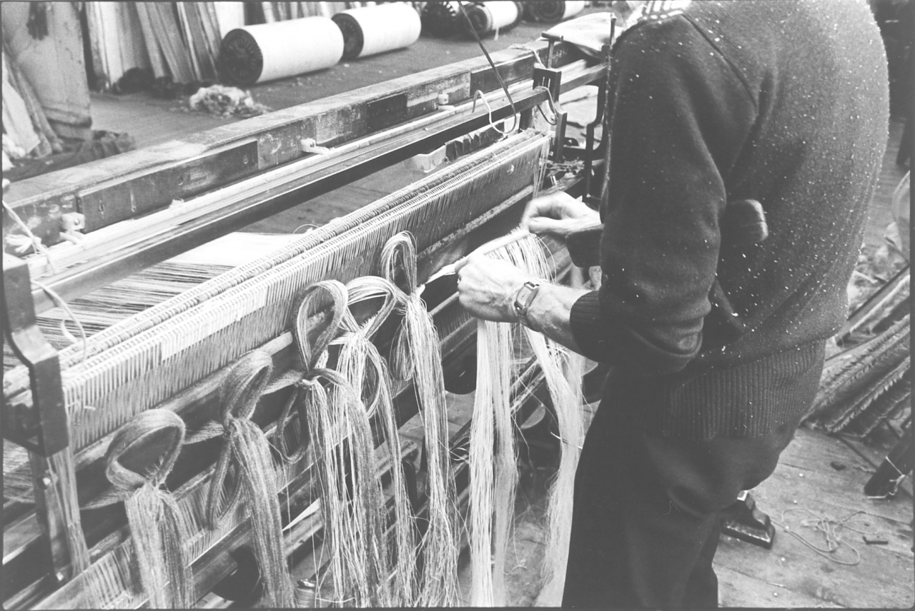
Picture number 33/34. Negative number 7717922/23.
We are now getting to the end of the process of drawing our warp. Jim has drawn all the ends through. When he has drawn all his ends through, what he does then is tip his reed up and trap it in the unused heald cords at each end so that the reed lies flat to the healds. Notice that he has drawn more of the sheet through. This is to check that all his ends are running free and to give him enough lease to knot the ends up. Notice also that he has taken the bar out of the two hooks on the frame. The sheet is going straight back to the warp. On picture number 34 he is knotting a bunch of ends up. Notice that under his arm is a brush. Before he knots these ends he brushes them. The action of brushing them gently pulls each thread to the same tension as its neighbours and once he has brushed them out to his satisfaction he ties them in a knot to stop them slipping back through the reed.
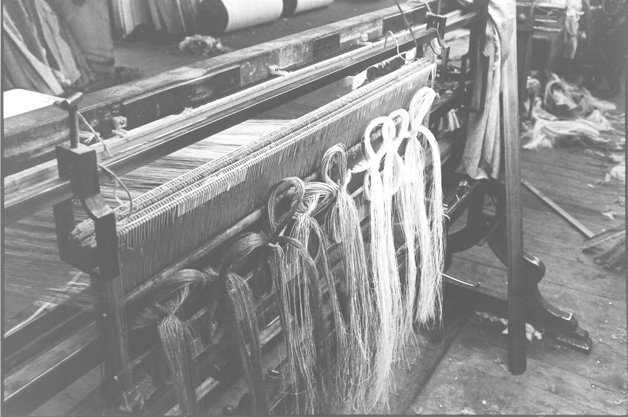
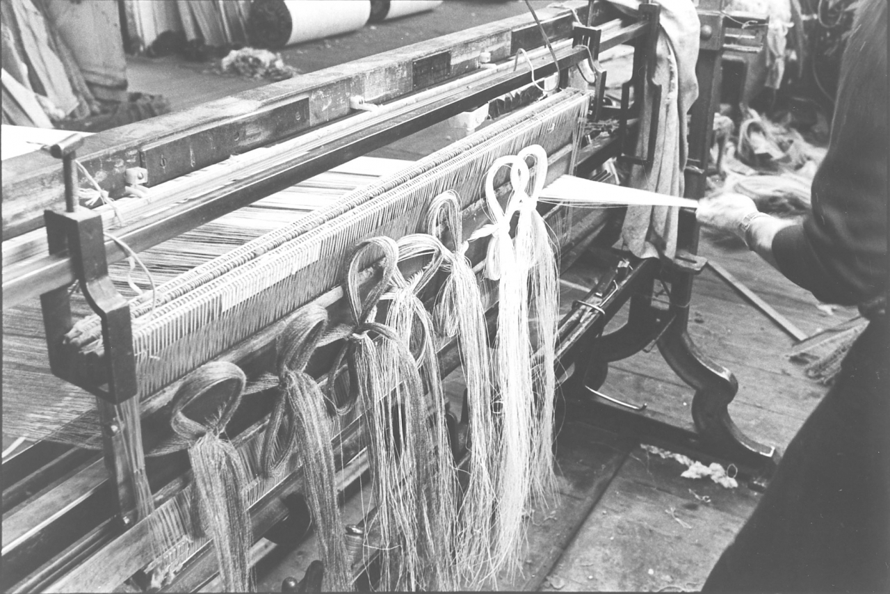
Pictures number 35/36. Negative numbers 7717925/24.
In picture number 36 he is actually brushing the ends and you'll notice that his hand has beaten the camera shutter. In picture 35 the warp is finished and ready for taking out of the looming frame. Yes, I got them out of order! Sorry.
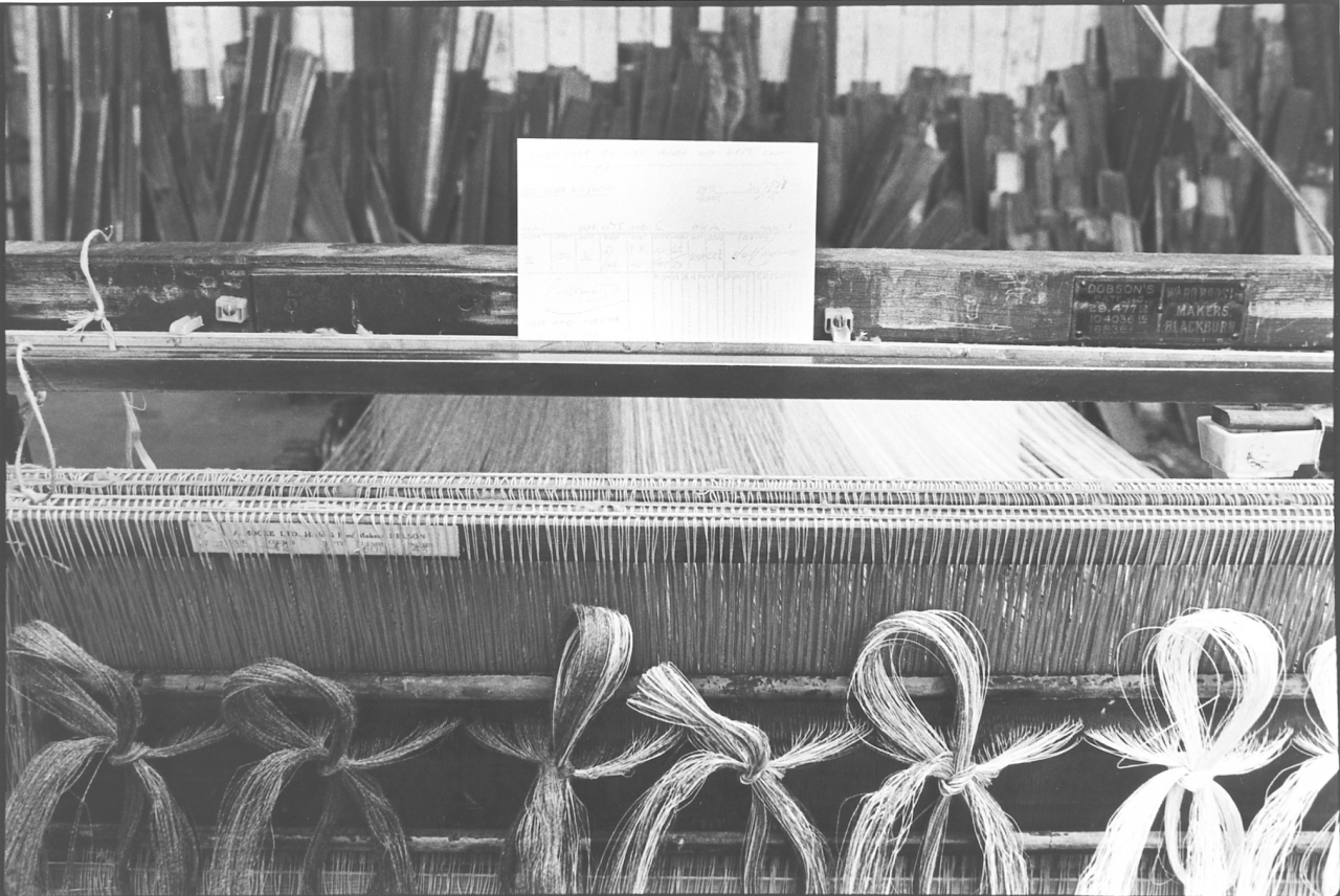
Picture number 37. negative number 7717928.
This is the warp card made out and ready to be trapped under the sheet when the warp is readied for the tackler. The warp card is a piece of stiff card which follows the warp right through its progress through the mill. It contains all the information necessary for the tackler, the weaver and the warehouseman. The weaver is paid off that card, it's presented in the office each time a cut or a length of cloth is cut out of the loom and the weaver is paid a bonus on time rate of so much for each hundred picks. A pick is one complete move through the loom of the shuttle. This card tells the weaver also a lot of other things. It tells them what sort of weft they ought to be using in the shuttle, it tells them whether the cloth is pickfound or not and gives instructions to the weaver in other ways like 'loose ends must be pulled off' and 'weft tags must be pulled off'’. It's a complete record of that warp and as follows this warp right the way through the process until finally when the warp is woven out it finishes up in the office and is then used for booking up production figures in the office. Then of course it is thrown away.
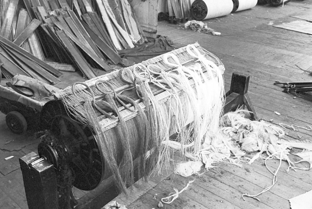
Picture number 38. Negative number 7717930.
This shows the warp that Jim’s been dealing with on the stocks when he’d actually finished with it. You'll notice that Jim has laid the healds and reeds on the warp and fastened them on with a piece of thrum, you’ll see it in the middle, a piece of banding. That is the condition in which that warp will be when it is collected by the tackler for gaiting into the loom in the shed. We shall follow this warp later when we come to describe the tackler’s pictures.
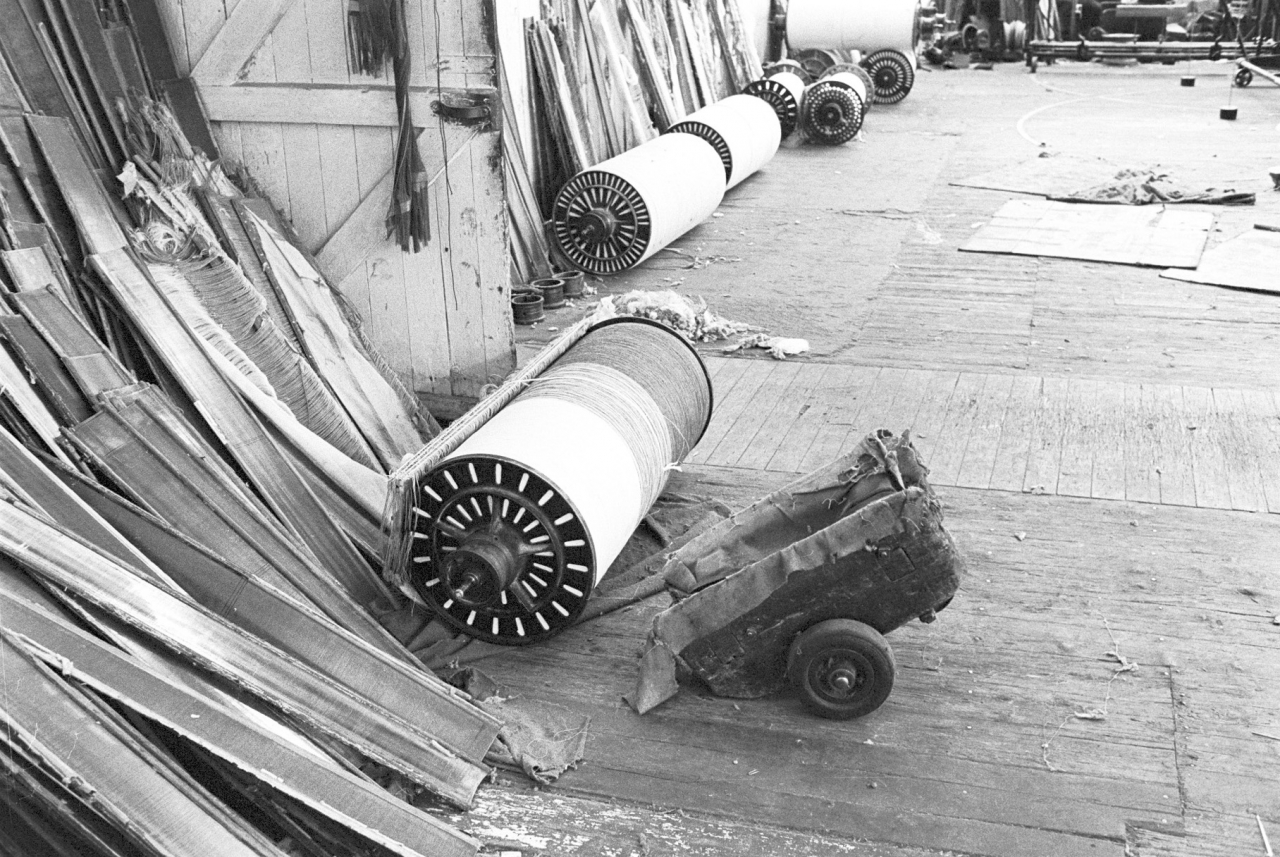
Picture number 39. negative number 7717934.
Here is the warp ready for going down to the shed. Imagine what this floor looked like when say 400 warps had been downed in the same week. This was not an unusual figure in the old days.
This completes the description of looming. We shall go into the shed now and have a look at the weaver.
DESCRIPTION OF THE WEAVING PICTURES IN THE BANCROFT FOLIO.
Every worker in the mill was important but the weaver is the bedrock of the industry. It was the need to weave cloth which was the genesis of everything else. In terms of numbers, amount of work done and economic benefit to the industry, the weaver was king, or in modern times more likely to be queen. Conversely, in terms of pay and conditions of work the weaver was very badly treated. Much of this stemmed from the fact that a large proportion of weavers were women. Much has been written by academics about the fact that women weavers were well paid relative to other women workers in society but this was only because men worked in the same job and there was never any differentiation between sexes in the shed in terms of pay rates.
There is much in the body of transcripts in the LTP about weavers. Mary Wilkins herself was interviewed, 79/AF series, but there were problems with this, it was against her husband’s wishes. Ernie Roberts and Jim Pollard give a lot of information about the weaver’s work and this description by me of the pictures will help as well. Mary Wilkins was regarded by Jim Pollard as one of the three best weavers in the shed. First a word or two about Mary and about weaving in general. Weaving, in common with every other job in the mill, is a very skilled job. One of the tragedies about weaving is that it has never been recognized as such. I have often thought that this stems from two facts, one is that up to the beginning of the second world war weavers were ten a penny and anybody could get as many of them as they needed and so they weren’t very highly regarded. Second, I think, is something to do with the fact that most of them were women. I think the view that was taken was how could a woman be a craftsman? Be that as it may, my opinion of the job of the weaver is that a good weaver is certainly a craftsman or craftswoman. A good weaver is a treasure; and believe me there aren't many of them about. Anybody that wants to go further into the reasons why there are good weavers and bad weavers should listen very carefully to Jim Pollard and Ernie Roberts talking about weavers.
Jim Pollard puts a lot of the troubles of the industry today down to the fact that not enough attention has been paid to the training of weavers. In particular to the fact that just after the war when the slogan ‘Britain's bread hangs by Lancashire thread’ was commonplace weavers were trained in as little as three weeks before they were running their own looms. It certainly is true to say that the good weavers that are about nowadays are almost all people who learned their trade either before the war or during the war. There are very few good weavers about who have learned the trade since the war. It's as simple as that. If there are, and Mary is one of them, it's because they were born weavers anyway, they were born with the skill in their fingers. There is much to be said for the point of view that good weavers are born not made. They are a certain type of person. They are a person who is generally fairly lightly built, find it very difficult to keep still, are very active, for ever on the go and one further attribute they have got to have, especially working on Lancashire looms, is that they have got to be hungry. When I say hungry, not necessarily physically hungry, but they have got to want the money; because they have got to have an incentive to work. When one looks at conditions in a weaving shed, even nowadays and I dare say in a hundred years, these pictures will just seem fantastic. Because the conditions in the weaving shed are so atrocious that one wonders why people stand it. This of course is showing up in the industry nowadays in the fact that it's very hard to get weavers to work on Lancashire looms, people just aren't interested. Things like noise levels, dirt, responsibility, and the level of sheer hard work that has to go into the job militates against people taking up the trade nowadays. The stock example we have in Barnoldswick at this time is that a woman can go down to Rolls Royce and earn £55 a week just for sweeping up.
Let’s look at the pictures bearing in mind that a weaver’s task is to keep her looms running as near non-stop as she can. Mary’s wage is made up of a fixed payment and then a bonus of so much for every 100 picks registered on the pick clock on her loom. The actual reward for each 100 picks is specified by rules laid down in the Uniform List of Prices. This is an agreed scale between the manufacturers and the Unions which applies to all the weavers in North East Lancashire. Her main task is shuttling, taking the empty shuttle out of the loom, inserting a full one and replenishing the weft package in the empty shuttle. Each loom has two shuttles, one in use and the other ready for use in the shuttle stand on the loom.
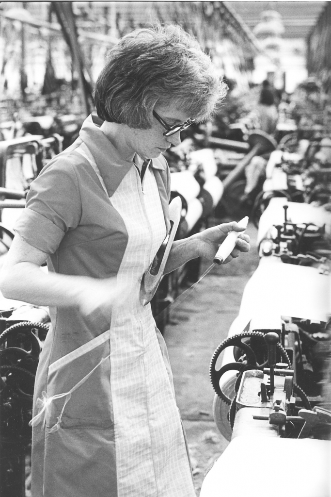
Bancroft folio, weaving picture number l. Negative number 7717734.
This is a picture of our weaver, Mary Wilkins, readying a pirn before installing it in the shuttle which is under her left arm.
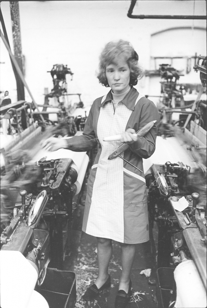
Picture number 2. Negative number 7723425A.
Here we have Mary stood in her alley with a seemingly far-away look on her face. She is working almost in a trance. A good weaver can do the job almost without thinking. It gets to be very nearly automatic and it's possible for her to let her mind wander on to all sorts of subjects whilst she is actually weaving. I found this was true while I was driving. I think that if you're really at home with a job and good at it there's no need for your mind to be working a hundred per cent on making sure that you do the job all the time. You can let your mind wander, function on automatic pilot and allow your mind to go off on to different subjects altogether which is what Mary's doing here. She could be thinking about anything, what she is going to give her husband for tea, the colour of her new curtains, anything at all. In point of fact the job that she is doing while she daydreams is preparing a shuttle for the loom.
The weaver’s job consists almost entirely of what we call shuttling; in other words taking out empty shuttles and replacing them with full shuttles. Her job is to keep the looms running and it's as simple as that, to keep cloth rolling off but also to weave good cloth. This means picking up any faults as they occur and keeping those looms running. The sign of a good weaver is that she is sat at the end of her alley and the looms are running away merrily. How much of this free time she had depended on the count and quality of the weft. If she was on fine weft a shuttle could last 15 minutes so with ten looms she could get away with 40 shuttle changes an hour which gave time for a breather but was a lower bonus on the pick rate. If she was on heavy yarn she could have 120 shuttle changes in an hour and no time to sit. Mary preferred these sorts, she was into earning not sitting. You'll notice that she is holding in her hand what we call a yarn package which is a wooden pirn which has the weft or thread on which passes across the loom through the threads of the warp She's got that in her left hand and she's also cradling the shuttle in her left arm while she is pulling off thread from the bottom of the pirn. In order to weave successfully in the loom the weft has to unwind from the narrow end of the pirn. So you might wonder why she is doing that, pulling weft off the base of the package. This is a sure sign of machine wound weft, rewound weft.
At Bancroft we used Leesona and Britoba pirn winders. All our weft was rewound at by us from the spinner’s package, via a cone winder on to pirn winders. The reason it was put through these processes was that this eliminated weak shops in the weft because the yarn broke during the process of re-winding, and it produced exactly the right size of package for our shuttles. Rewound weft was the surest way of minimising weft faults at the loom and therefore cut down on efficiency losses. A characteristic of pirn winders is that when they finish building a package they wind a couple of turns on the base of the spindle so that the weft is feeding in the right place to start the new pirn. So the first thing the weaver has to do before she loads that shuttle is pull off the thread until it is feeding from the tip of the package. You can see it flying off in her hand. Notice in the pictures that there are two full shuttles laid on the shuttle stands of looms that are running. One stand is empty, she will place the shuttle she is dealing with on here. The stand on the right is empty. This is almost certainly because her tackler is repairing or adjusting that shuttle for her. This no problem because if you look the cloth on the roller is cut out. This loom is waiting for a warp. Mary is paid stopped time for that loom while it is empty. On that stand you can see a small piece of sandpaper. If Mary catches a shuttle on a metal part she will rub it down with that to keep it smooth. Also on the stand is what looks like a small handle. That is a hook very similar to the one that Jim uses for looming, but it's longer and has a bend in it. Mary uses that for drawing any ends of the warp through the healds and reed which has ‘gone down’, which she is replacing because it has broken. It’s a reed hook and heald hook combined so it's very thin and whippy to go through the dents in the reed. You'll see her later on using that to take an end up.
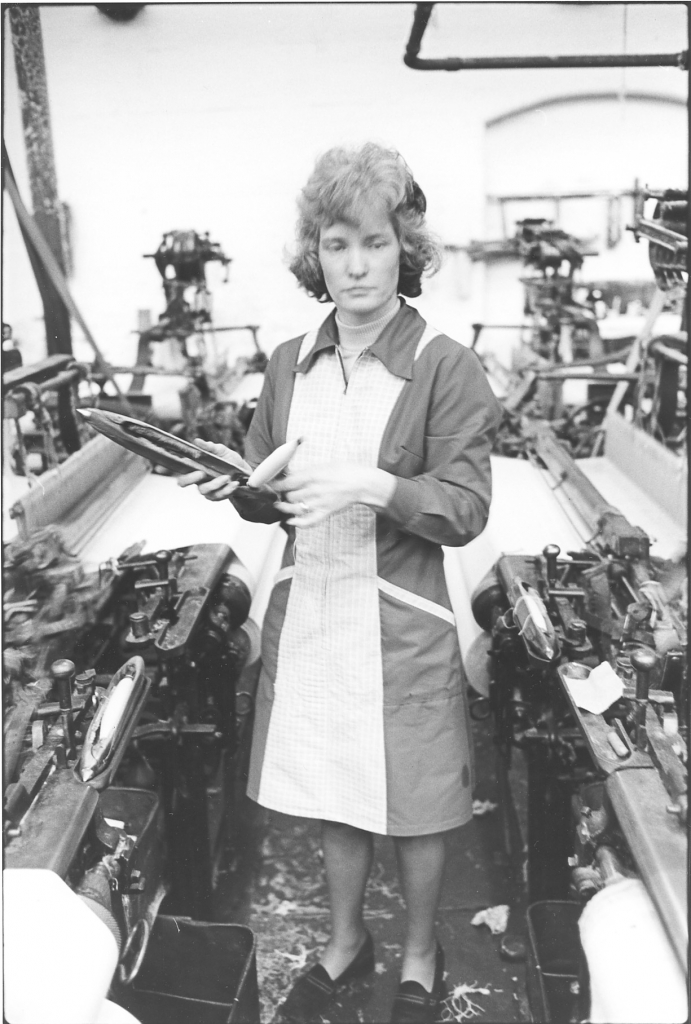
Picture number 3. Negative number 7723426A.
Mary’s hands are moving so quickly that it’s just not possible to take photographs fast enough to keep up with her. What she’s done, remember she was holding the pirn in her left hand and the shuttle was under her left arm with the peg opened and facing the floor. The shuttle peg is the metal prong on which the hollow pirn is mounted. Once she’s finished drawing that thread off, she keeps hold of that pirn with her left hand, reaches across her body with her right hand, gets hold of the body of the shuttle, pulls it off her arm and then pushes the peg up through the yarn package. Of course the pirn has a hole through the middle of it. Notice that I have said she pushes the peg through the pirn. This is a throw-back to the days when Mary started weaving when paper tube packages were delivered straight from the spinner to go on the loom. It was very easy to ‘stab a cop’ if you pushed the package down on to the peg. [The prong piercing the side of the weft package instead of following the centre to the end.] The way Mary was taught was to hold the package still and skewer it with the cop by rotating the shuttle as it entered the cop. This doesn’t matter with full pirns but Mary still does it the way she was taught. She is drawing some yarn off now and at the same time her hand is starting to move over to close the peg carrying the yarn package down into the shuttle. As she does this she drags the thread over the slot in the end of the shuttle which threads the yarn through the eye of the shuttle.
One other thing to notice about that shuttle is that the top end of it is lined with fur. This controls the weft as it is being dragged off the package by the passage of the shuttle through the loom. If this fur wasn’t there the yarn would tend to balloon as it flew off the package and snarl up in the eye of the shuttle thus causing a break and wasting time.
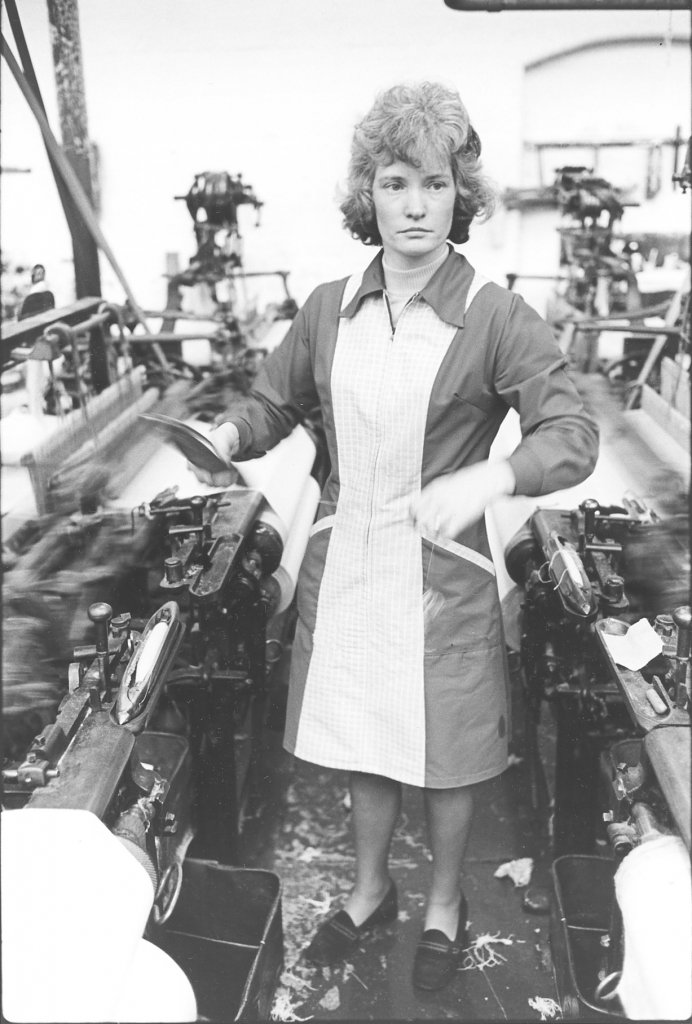
Picture number 4. Negative number 7723427A.
Having installed the package and threaded the shuttle Mary is pulling off a yard or two of yarn to ensure that it is running freely. Notice that her gaze has shifted. She is subconsciously checking on her looms as she prepares the shuttle. Incidentally, you’ll notice that in all these pictures of people doing their work they are not reacting to me and the camera at all. This is because I took literally thousands of pictures and they had got so used to me using a camera that I was part of the scenery.
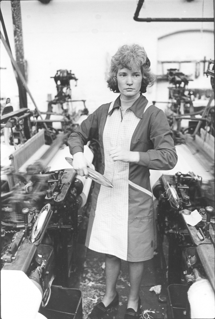
Picture number 5. Negative number 7723428A.
In this picture Mary is wrapping the loose end of the yarn round the shuttle so that it doesn’t hang down on the loom and perhaps get caught up in the motion.
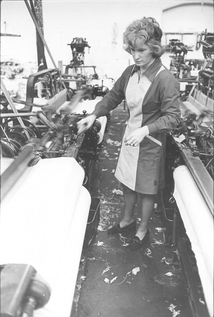
Picture number 6. Negative number 7723429A
If you have eagle eyes you will see that I have cheated here. Mary is putting the refilled shuttle back on the loom but it’s not the same loom that she was working on before. I missed this shot and as the next shuttle had just run out I waited until she was putting the shuttle back on this loom. Notice that the mechanisms on the loom are clean and so is the floor apart from the loose ends of balled up yarn that Mary drops while she is shuttling. She will sweep these up at lunch time. It is a waste of time to keep walking down to her waste tin and throwing them in.
Pictures number 7/8/9. Negative numbers 7723430A/22A/31A.
These three pictures are of Mary starting a loom. Number 8 is actually a different loom than the other two but the operations are in order. She has changed the shuttle. Now, what she is doing in number 7, she's taken the empty shuttle out, you can see it in the tray on the loom, and she’s putting the full shuttle in. Now what she has to do is push that shuttle right down into the box as far as it'll go. To do that she reaches over behind the shuttle box and eases the spring on the box with her right hand and with her left hand, with the second finger she just pushes that shuttle home into the end of the box. Sometimes she uses a small metal rod on a handle to do this if a swell spring is tight. The reason why the shuttle has to be pushed right home on the picker is to make sure it gets a full blow on the first stroke of the picking stick to ensure that it travels the full width of the loom.
On number 8 she has her right hand on the knocking on lever and her left hand on the slay or ‘hand shelf’ to give it a good kick off. She doesn't just rely on the machine driving it, she helps it off and she is just about to set that loom on. You can see the shuttle in the box.
In picture number 9 she has done it. The loom's away, you can see that it's blurred and what she is doing is pulling off the weft tag which she has trapped in the cloth at the far side. In other words when she loaded that loom she put the shuttle in at the place where the last one had run out. This is known as ‘finding the pick’ and such a cloth will be noted on the warp card as ‘pickfound’. The loose end of weft that is left hanging out of the cloth where the shuttle was inserted is called a ‘weft tag’ and is the reason for the instruction on the warp card, ‘weft tags must be pulled off’. She either cuts it with her scissors or sometimes just pulls it off with a pair of flat ended tweezers. In this way it is impossible to see a mark in the cloth where one shuttle ran out and another one started. This could only happen on a Lancashire loom run manually. If by chance the weft ran out at the selvedge or if it wasn’t a pickfound cloth Mary would anchor the loose end of the weft under the temple to hold it while the loom started. The temple is the small metal clip on each side of the cloth between the place where the shuttle is running and the breast beam of the loom. This small housing holds a brass roller with metal spikes in which is offset to the cloth in such a manner that as the cloth passes through the grip of the roller it is pulled out sideways to stop the cloth contracting in the shed where it is weaving. If this wasn’t done the cloth would not weave as it would be trying to get narrower. This contraction is caused by the action of the weft in the warp and is a characteristic of any weaving operation.
On the early automatic looms the box just loaded a full shuttle at the end of the shed no matter where the weft ran out so there was always a small mark on the cloth. On later models they put a small feeler on that detected when the pirn was about to run out and stopped the loom so that the weft tag was always on the selvedge. This meant that there was always a small amount of weft left on the pirn which was waste but it avoided a pick mark in the cloth.
Picture number 10. Negative number 7723539.
The next seven pictures show another routine shuttle change but this time all doesn’t go well. In picture 10 Mary is putting a freshly loaded shuttle into the box ready to start the loom up again.
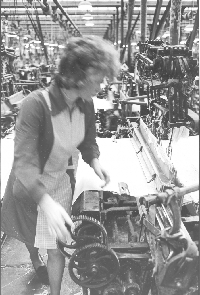
Picture number 11. Negative number 7723540.
Here Mary is reaching down towards the gear wheels at this side of the loom and what she is going to do there is something that she does every time she re-starts a loom after she has changed the shuttle. She just lets off the tension on the cloth a bit otherwise she'll get a thin place on the cloth where she starts. She just lets it off two or three clicks depending on the type of cloth she has got in.
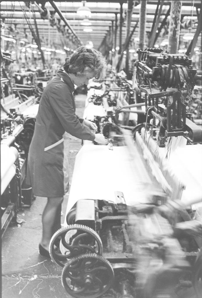
Picture number 12. Negative number 7723541.
Mary has started the loom and is pulling the weft tag off from under the temple.
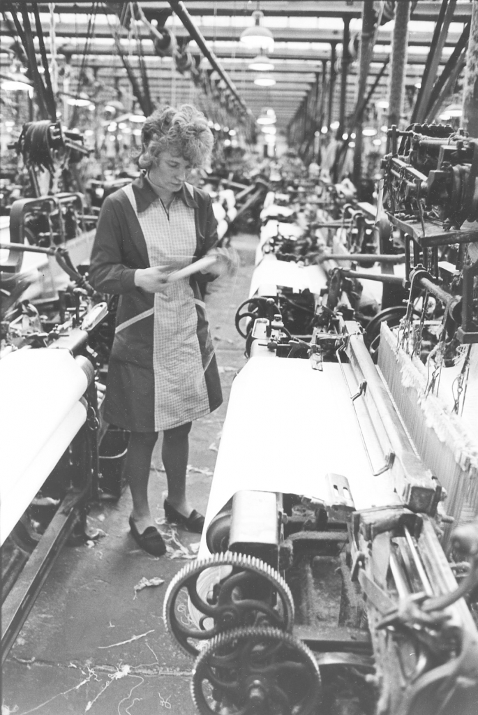
Picture number 13. Negative number 7723542.
Here Mary is refilling the shuttle she has just taken out of the loom but while she is doing this the loom stops. The weft stop motion has detected that the weft has broken.
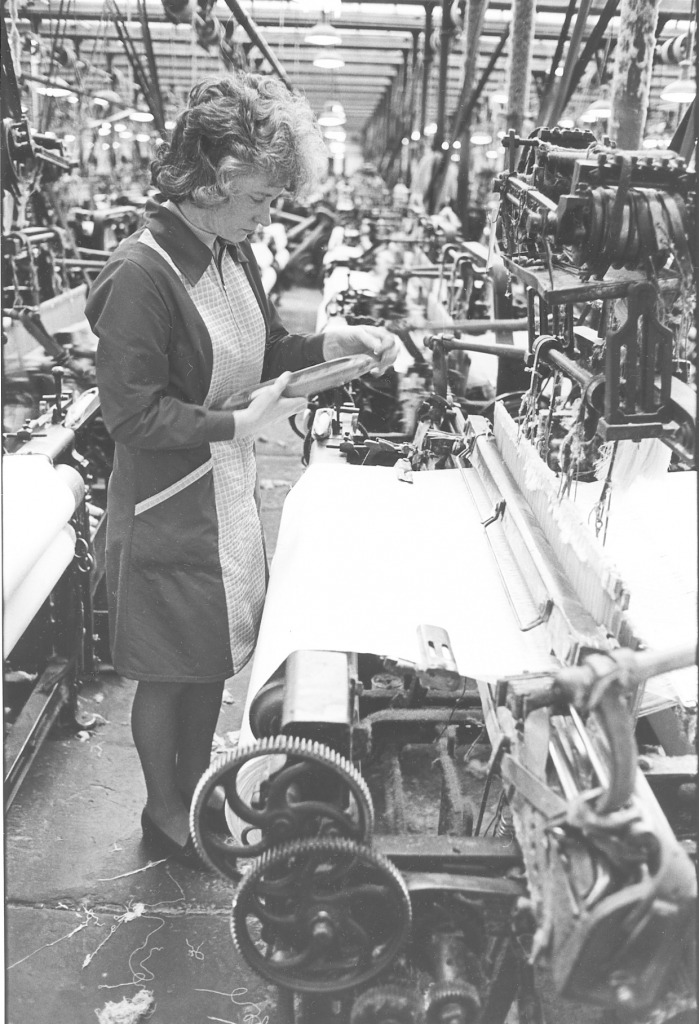
Picture number 14. Negative number 7723500.
Here you can see that Mary has put a new package in the other shuttle and placed it on the shuttle stand. She has taken the other shuttle out of the loom and is examining it to see what is wrong. She draws some thread off it. Now you'll notice there isn't a lot of thread left on that pirn, you can see just by the back of her right hand. Now a lot of weavers wouldn't have bothered doing that, they'd have pulled that pirn out, thrown it into the waste box and started with a fresh shuttle straight away. But Mary is a good weaver and she likes to weave all her pirns off; she has been brought up in the old way not making much waste. So, instead of just taking the easy way out, she is finding out why it's not run off, why that pirn hasn't run off properly as it should have done. And if I remember rightly, I mean this was in 1977, it's two years ago when it happened, but I think if I remember rightly it was because it was just a bad place in the thread. What we call a thick shop in the thread which had caught in the eye and broken the weft. Anyway, she draws a bit off and in the next picture we’ll see her popping it back in where it broke.
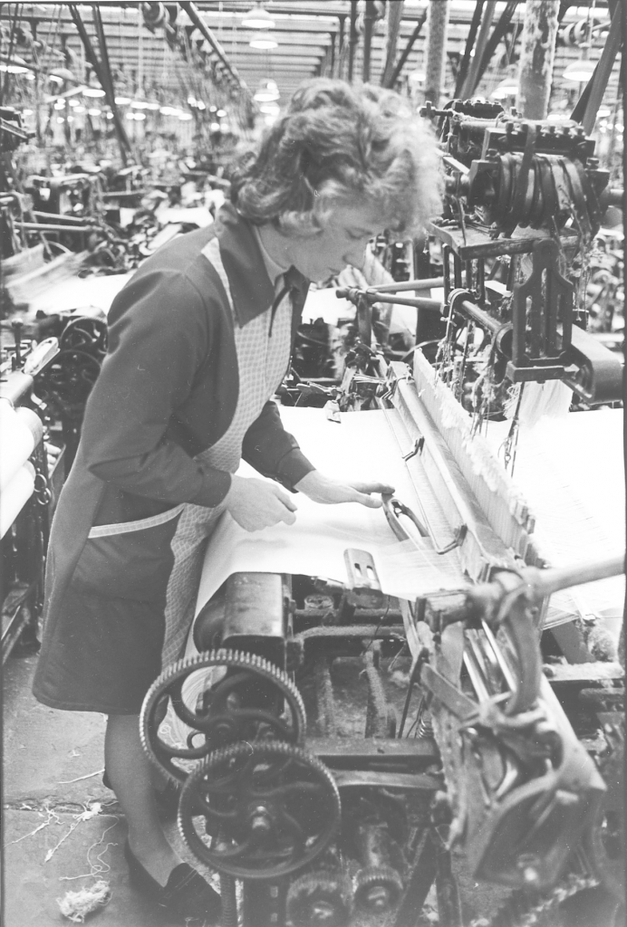
Picture number 15. Negative number 772350.
Here she is putting the shuttle back in where it ran out. Now it gets a bit complicated here. The weft broke just before the shuttle was entering the box at this end. Now this is the wrong end for a loom to stop, A Lancashire loom should always stop with the shuttle in the box next to the knocking on lever. We are looking at a bit of top class weaving here because Mary is putting the half empty shuttle in and pushing it into the wrong box for starting because this is how it was travelling when the weft broke. There is no picture of it but when she gets it into this box she throws the loom over by hand to alter the shed and then flicks the shuttle through the thread into the box at the other end.
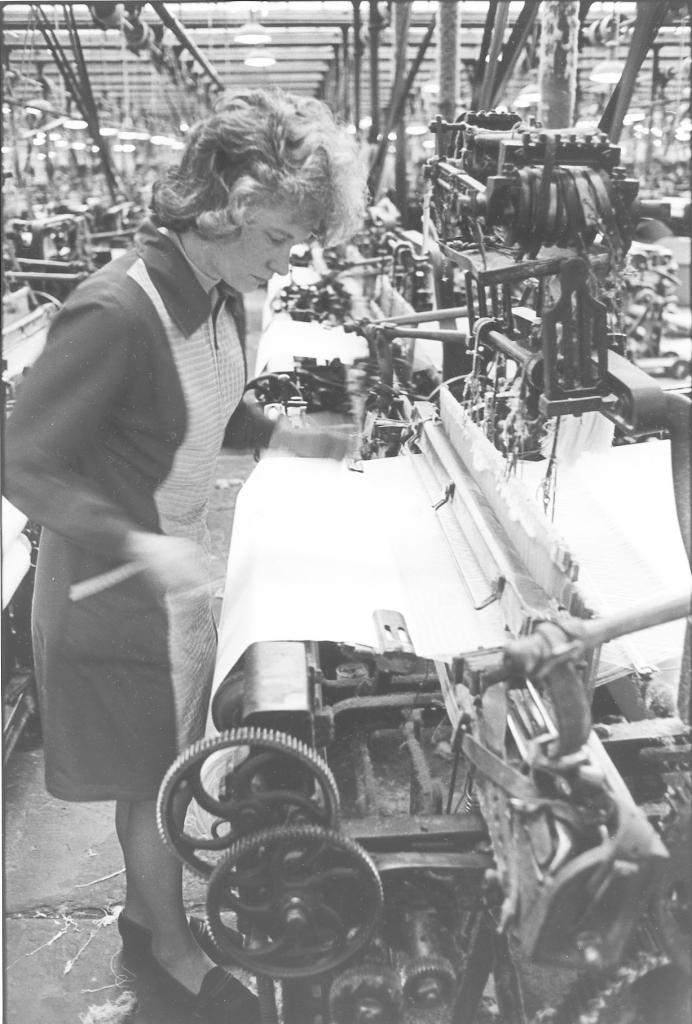
Picture number 16. Negative number 7723501.
The shuttle is in the far box and Mary is moving towards the cloth take up motion to let it off a couple of clicks before restarting the loom.
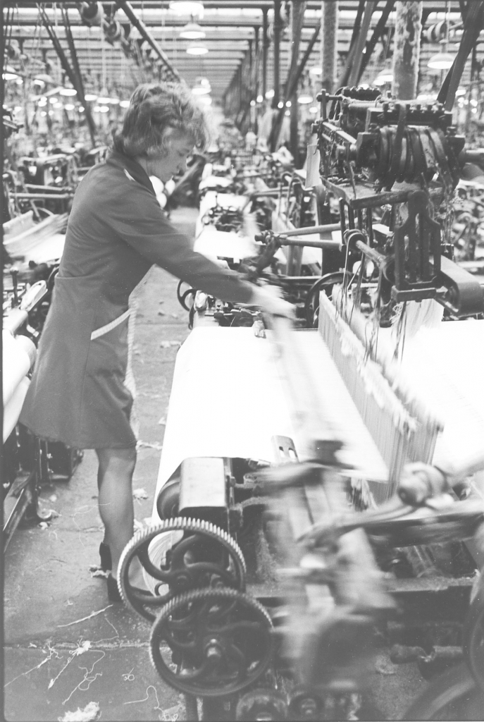
Picture number 17. Negative number 7723502.
Here she is setting the loom on. Remember this is a left hand loom, the knocking on lever is at the far end so she’s got her left hand on the lever and her right one on the hand shelf. The loom is away and running. That little set of pictures says a lot about Mary which of course is the reason why I put them in. A lot of people wouldn't have bothered, they'd just have banged the fresh shuttle in and away and that's it. But not Mary, she is a good weaver, she is trying, so she does the job right. Notice the dawn on the healds in that picture and the way it’s collected on the pillars round about. A lot of dust floats about in a weaving shed, not as much as people think but enough to make things very dusty at times.
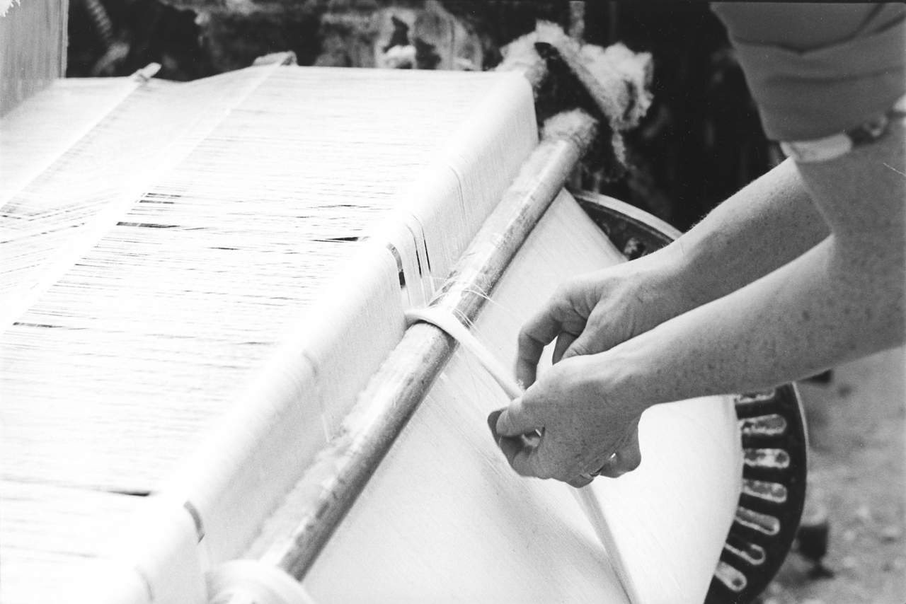
Picture number 18. Negative number 7717720.
This is a different kettle of fish altogether. If you remember when we were talking about making up sets of back beams to make weavers warps we said that very often there was a spare end, or perhaps even two or three spare ends in a warp. Well what we are looking at here is a spare end on a warp and the way the weaver deals with it. Many a time during the course of weaving a warp one end might go down badly, or keep breaking. In that case the spare end is brought across and used to replace that bad end. But in the meantime while it's weaving you have got to do something with the spare end, so what you do is take it back round the warp and as the warp winds off the spare end keeps winding through in the same place. Now obviously those threads are going round and round but the rest of the warp's winding forwards and it gradually builds up until you have got a fairly thick rope of weft on the warp. Every now and again the weaver will cut that off and let it start afresh if it starts to get too thick. Or, as in this case, she might decide that she needs that end. In that case she will cut it and just take that end off, and take that end through with the rest of the sheet and use it to piece up.
Picture number 19. Negative number 7717717.
Here Mary is doing something which is one of the biggest parts of the weavers job. She is taking up an end that's gone down. Notice she has got her tools there, a pair of scissors on the cloth and a reed hook in her hand. She has reached over with her right hand behind the heald and she has found the end that's loose and tied another piece onto it to make it the right length for drawing through. She puts her reed hook through the eye in the heald where that end should be coming through and hooks into the thread as she is holding it with her right hand and draws it through the heald.
Picture number 20. Negative number 7717718.
Here she is doing the same thing again but she is drawing the end through the reed. She’s got hold of it behind the reed and she is pushing her reed hook through to pick up the loose end.
Picture number 21. Negative number 7717719.
She’s drawn the end through and is trapping it under the temple. Normally she'd just leave it hanging loose because she wouldn’t be near enough to the temple to do that, but in this case the end's gone down very near to the temple so she reaches in and traps it there. Then she sets that loom on and lets it weave off. Here again she will pull the tag off to leave the cloth perfect.
Picture number 22. Negative number 7717731.
This is a picture of Mary taking an end up again. She's just drawn the end through the heald, but this picture is from the same side as Mary. This is a typical attitude in a typical job that a weaver has to do. You’ll see them doing this many times during the day and for this reason the weaver is said to spend most of her time putting right other people's mistakes. There again, an interesting picture, a lot can be picked out of it. I'm not going to go into too much detail at the moment because a lot of this will come out when other people are describing the jobs themselves.
Notice the polish on the hand shelf or slay cap of the loom there, where she normally places her hand when she's starting and stopping the loom. This is a similar sort of polish to the one that's on Jim’s looming hook, there is only one way to get it, use something regularly for years and years and look after it. Notice as well the warp card hung up on the piece of wire on the loom which gives the weaver all the information she needs about those warps. That card follows that warp and is hung up on the loom with it, and every weaver knows how to read the information on it and knows exactly what she is doing.
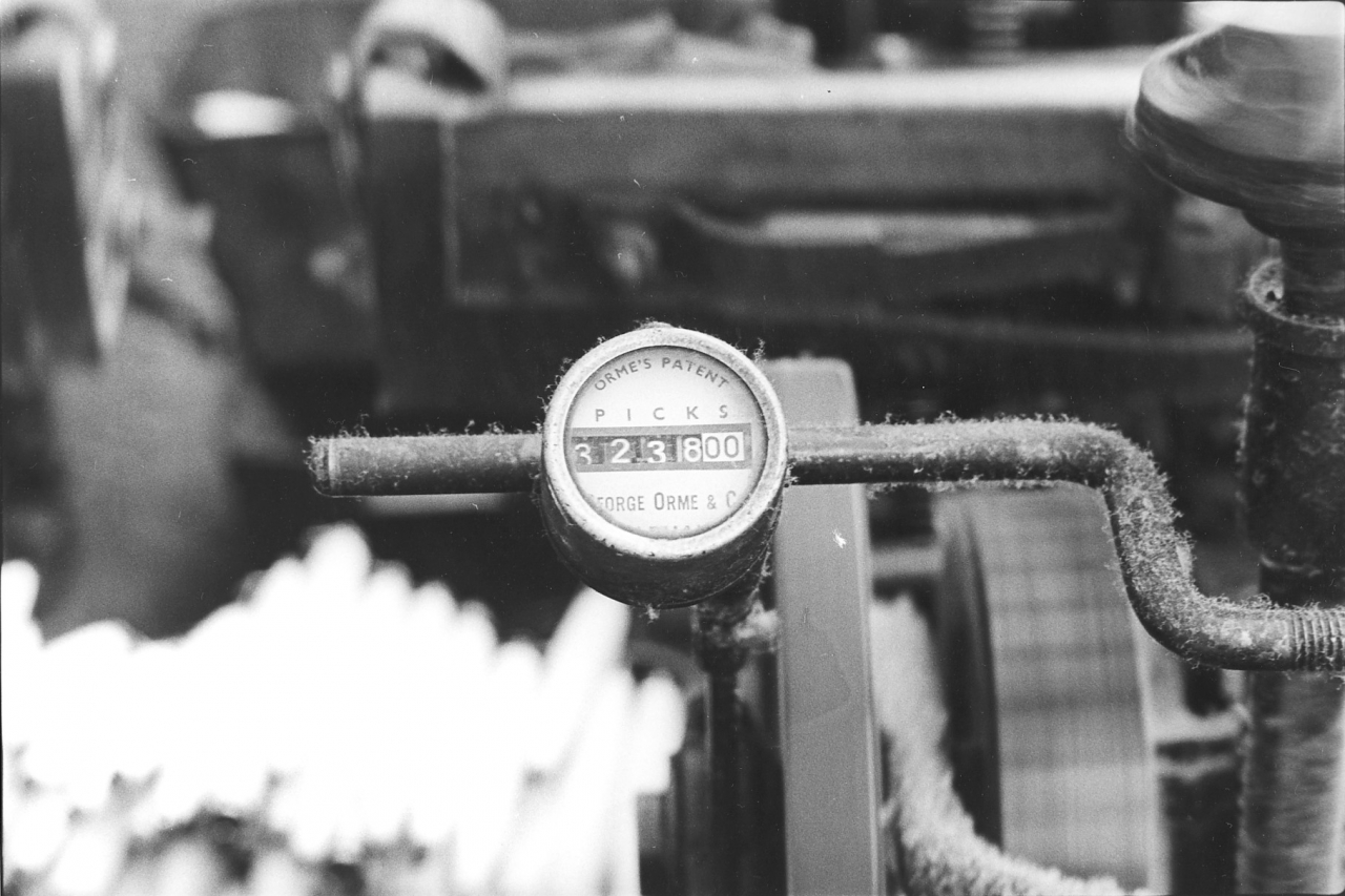
Picture number 23. Negative number 7717721.
This picture is so simple and yet a book could be written about it. The information that's contained in that one picture is just amazing if you care to do the necessary research. What you are looking at is a pick clock which is counting the number of picks in hundreds. In other words that clock is showing 323,800 picks. The pick clock is the method used to determine how much work a weaver has actually done during a shift or a week and she is paid off those figures and on a time rate as well. The weavers fought for years for pick clocks, and I think that it's true on the whole to say that when they eventually got them it didn't do them much good. They weren't the answer to everything as they thought they would be. As I say, the history could be written of the fight to get pick clocks introduced because the pick clock was essential to a different payment for cloth than just being paid by the piece. Until the introduction of the pick clock, weavers were paid by the piece and that meant that it was possible to work all week with bad warps and not get a single cut off the looms and consequently not get paid any money. This situation went on right up to the end of the second world war and people find it very hard to believe. Admittedly the management, out of the kindness of their hearts would give them an advance on the next week's wages but in point of fact it was possible to weave all week and not get any money.
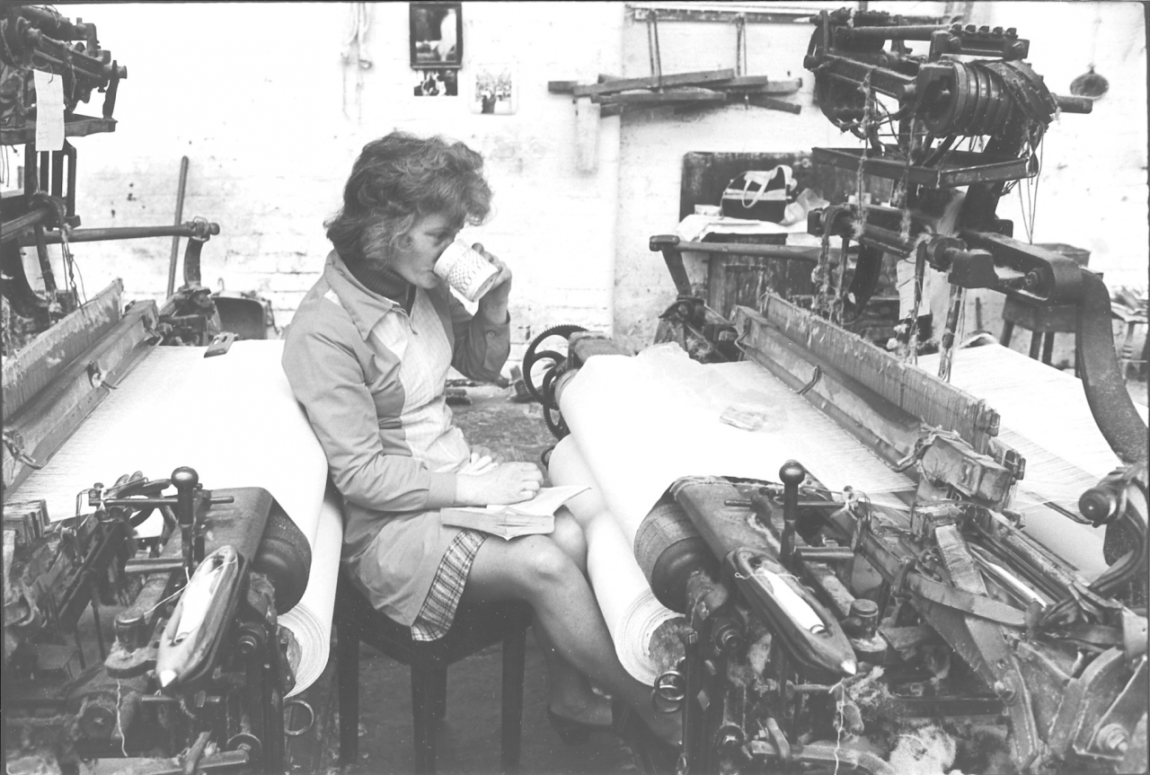
Picture number 24. Negative number 782101.
This is a nice little picture of Mary showing her taking her lunch. Again, a lot of information in this picture. She takes her lunch at the looms. We had a canteen with an oven in it for warming stuff up and a couple of benches but most of the weavers seemed to prefer to stay by the looms. By dinner time it was usually fairly warm in the shed. As you can see, Mary has got a buffet in between two looms and it's quite comfortable thank you. She is resting on the cloth on one loom, and she is using the cloth on the other loom as a table cloth, one thing about this canteen, it always has a clean table cloth. She has been down into the warehouse and brewed herself a pint of tea and she has got a book and she’ll spend half an hour there. We used to have an hour for dinner, but after consultation with the workers and the unions and we decided during the fuel shortages of 1976 that we’d make do with half an hour for dinner as it meant that we got away from the mill half an hour earlier at night. We finished at half past four instead of five, and it meant that we saved half an hours heating each day which was of course a saving on the coal bill. The weavers seemed to take to it quite well and in the end I think everybody rather liked this half an hour dinner break because it meant that the day was half an hour shorter really. A typical picture of a Lancashire weaver taking her break at dinner time.
I must say here that in common with Ernie, and anybody that's listened to Ernie Roberts’ tapes will know what he thinks about Mary Wilkin, in common with Ernie I have the greatest regard for Mary and people like her. I think that they are the salt of the earth. She was a marvellous worker, Ernie says that she is possibly the best Lancashire loom weaver he has ever seen and that must be a recommendation in itself. A most pleasing personality, spotlessly clean, always the same. When I say that I mean you could always be sure when you saw Mary that you'd get a smile, you'd get a kind word and if there were any complaints about anything they’d be put in a reasonable manner. She wouldn't be expecting you to move mountains in order to suit her. And really there is not much more you can say about somebody like Mary. With weavers like that I don't see how any business could fail.
Admittedly, Mary was one of the exceptions. She was one of our best weavers. But they were the people that I felt sorry for. In point of fact Mary left Bancroft before we actually closed down and the reason she left was that she got fed up with the dirty conditions and when you knew Mary it was very easy to understand that because she was meticulously clean in herself. She just couldn't stand the way things were deteriorating at Bancroft and things were getting dirtier and dirtier all round. And, well, really that's about all I can say about that. Very sad in some ways. I can't remember where Mary went working. I think it was to Johnsons in Earby. Where ever she went she was certainly a loss to Bancroft and I remember saying at the time, more prophetically than I ever dared think, that if people like Mary were leaving Bancroft then we might as well all bloody well leave because there was nowt for us - and by God, in the end that proved to be true.
SCG/22 September 2003
7,205 words.
LANCASHIRE TEXTILE PROJECT
TAPE 78/AI/10 (Side two)
THIS TAPE HAS BEEN RECORDED ON MAY 2nd 1979 AT 13 AVON DRIVE BARNOLDSWICK. THE INFORMANT IS STANLEY GRAHAM WHO WAS THE ENGINEER AT BANCROFT MILL AND WHO HAS BEEN THE INTERVIEWER ON MOST OF THE TAPES..
DESCRIPTION OF THE WINDING PICTURES IN THE BANCROFT FOLIO.
We’re moving on now into a less glamorous but no less essential process at Bancroft Shed. This the winding department which was presided over by the Winding Master, Frank Bleasdale.
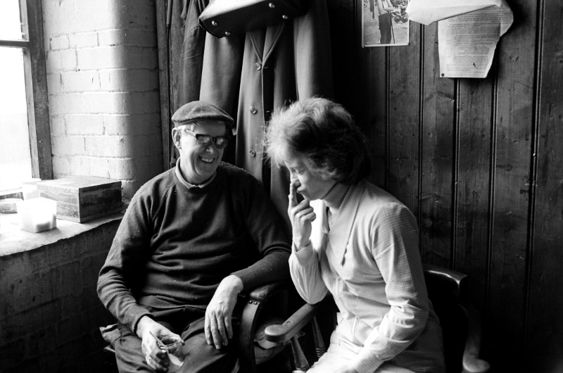
Frank having a brew with Mary Wilkin in the warehouse. This picture gives a good idea of the general relationship people had with each other at Bancroft. This is two friends enjoying each other's company.
Frank was brother to George Bleasdale who I took the engine over from. His department took in weft on ring package which was like a large pirn, transferred this to cone and the cones were then used to wind the pirns for our shuttles. This process reduced yarn faults in the weaver’s package and thus increased loom efficiency.
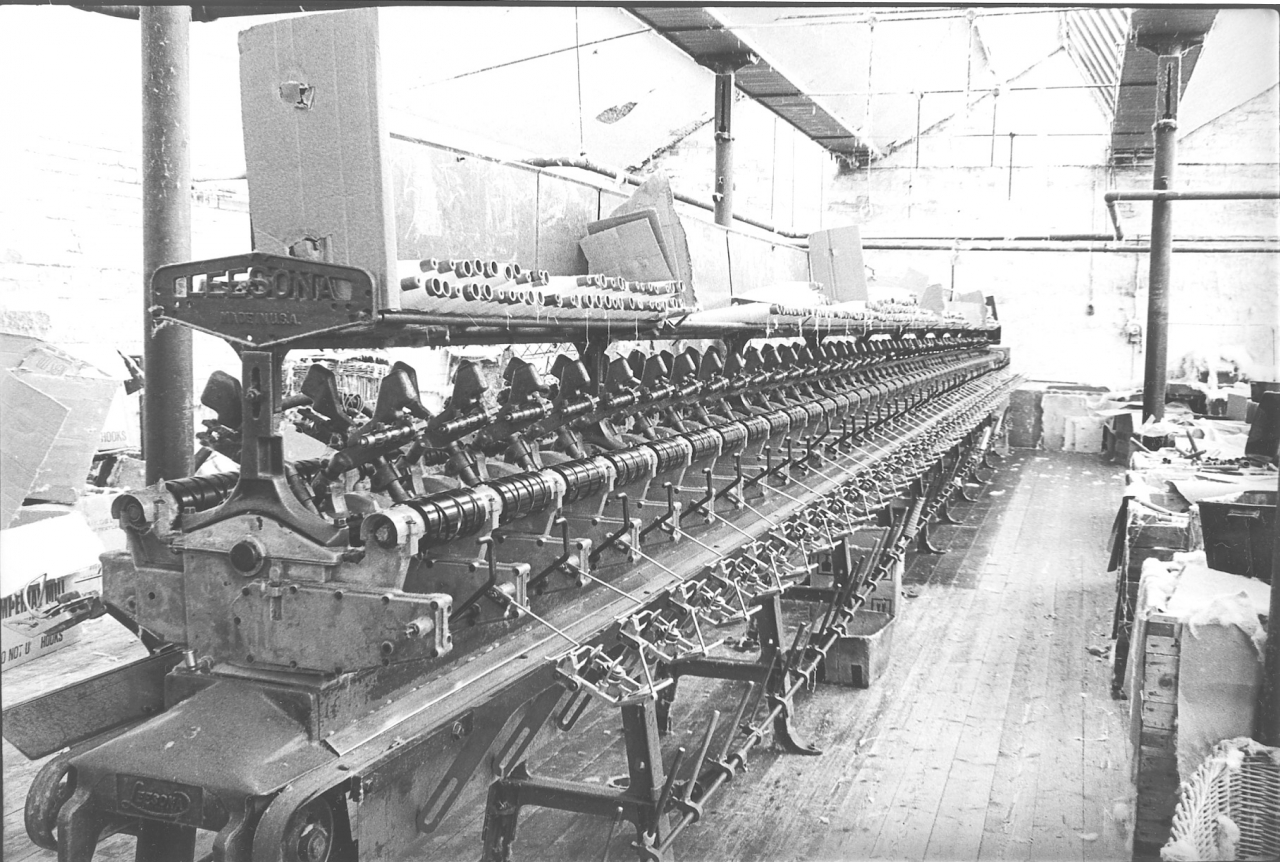
Bancroft folio, winding picture number 25. Negative number 7718022.
What we are looking at here is an old Leesona coning machine which converts ring tube yarn, which you can see on the top tray of the machine on to cone. There are no cones on the machine in this picture but we will see some later on. When I say ‘old Leesona’ this is because we bought this machine as scrap for £130 and set it up ourselves. Putting all the yarn on to one standard cone package was good for the automatic pirn winders as they could be set up for that package and never altered apart from minor repairs or adjustments for yarn count, package size etc.
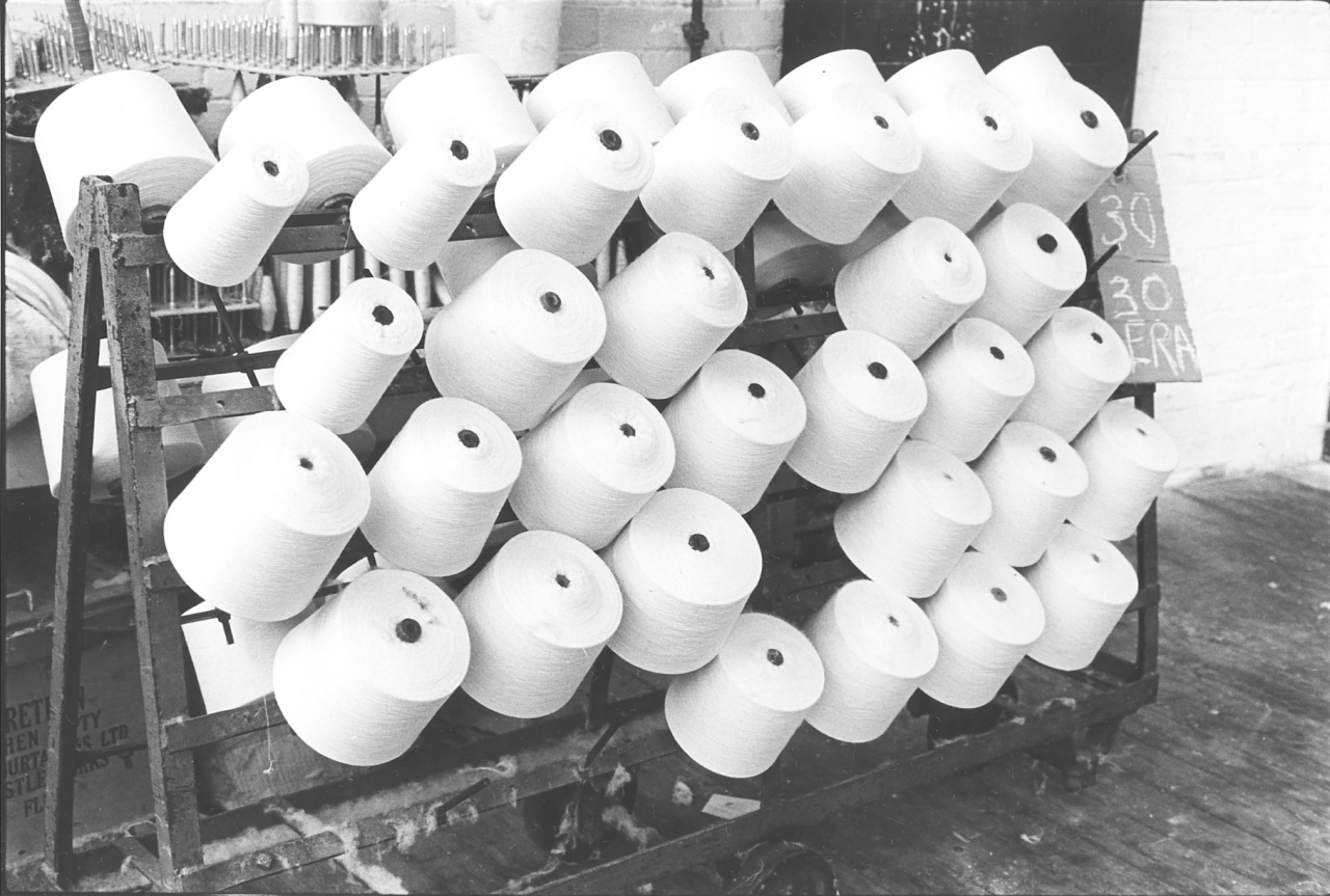
Picture number 26. Negative number 7722417.
This is a picture of a trolley with cones on which have come off the Leesona coning machine. The notice on the end, ’30 ERA’ is the count of the yarn and the mill in Rochdale it was spun at. [Two years after this was taken I was at Era Mill photographing the demolition and felling of the chimney.] These cones are ready to go on to the automatic pirn winders.
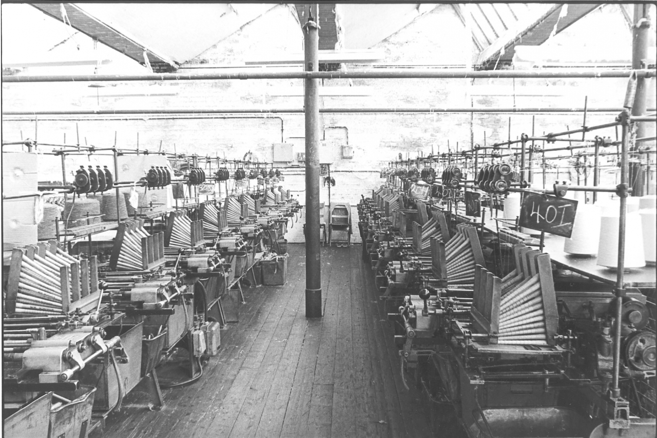
Picture number 27. Negative number 7718027.
This is a picture of the Hacoba automatic pirn winding machines. We bought these as scrap as well and installed them ourselves. You can see the magazines on top in which the empty pirns are loaded. Once the machine is set up and assuming there are no breakages, it will automatically carry on winding those pirns and dropping them into the tray at the bottom, the boxes at the bottom which you can see underneath each unit. They make a very good yarn package, we used to use the old Leesona 50 spindle winders which wound one pirn and then that had to he taken off and replaced by hand. In many ways these were the best winder that was ever invented because they made a beautiful yarn package. In fact we used to wind for other people on these machines. We eventually sold these machines owing to the fact that we found we could get almost as good a yarn package and certainly a lot cheaper in terms of labour off these automatic machines. We also found out that there was a market for the old Leesona machines down in Nottingham for people who were knitting and wanted a very good yarn package for the knitting machines to save stoppages. It seems that the Leesona Universal, the old 50 spindle frame which we used to use, I think it was called the Leesona 90 I'm not sure, I'm not really well up in winding machines, was regarded as the best machine that it was possible to buy even though they were all a tremendous age and second hand. We were selling them down in Nottingham for £50 each. Well, they were £50 apiece picked up at Bancroft so somebody thought they were worth something.
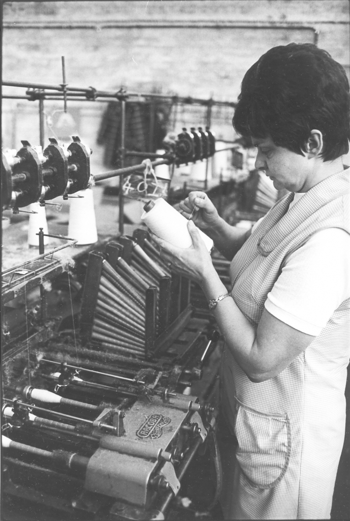
Picture number 28. Negative number 7721921.
Here is a winder working on one of the Hacoba machines. This is Jean Smith, one of the winders. There are very few pictures of winding here because winding is such a boring job, it's as simple as that. Winding is simply a matter of keeping the machine with full cones on top and magazines full of pirns and repairing any breakages that happen. All that's happening here is that Jean is winding on this machine and there has been a breakage. She has lifted the cone off the top and is examining the spool to see why there was a breakage. She pulls off some thread and breaks it off and then puts it back on.
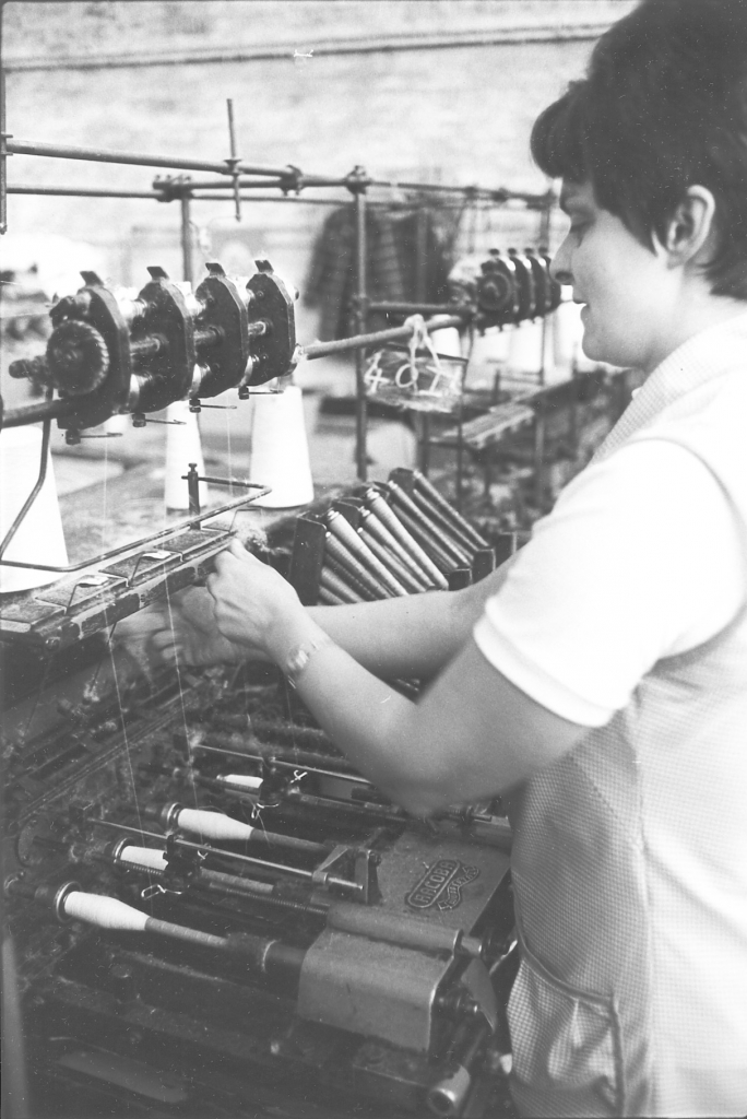
Picture number 29/30/31/32/33. Negative numbers 7721924/22/28/25/23.
These are simply pictures of her hands moving at tremendous speed to piece the yarn up, thread it through the various guides and get the spindle winding again.
A very limited set of pictures of a very limited job. That’s what a winder does all day is just travel up and down the machines keeping them running and keeping them fed with pirns and yarn. Funnily enough the winders are always regarded almost as the aristocracy in the mill amongst the women folk. It's always reckoned to be a very nice job to have, probably because they were slightly better paid than the weavers funnily enough and were reckoned to have an easier job. It was certainly less noisy and more pleasant to work in the winding room than down in the shed. This seems to be part of the hierarchy of the mill. I could never really understand it myself because there is certainly a lot more skill in a weaver's job than there is in a winder's.
DESCRIPTION OF THE TACKLING PICTURES IN THE BANCROFT FOLIO.
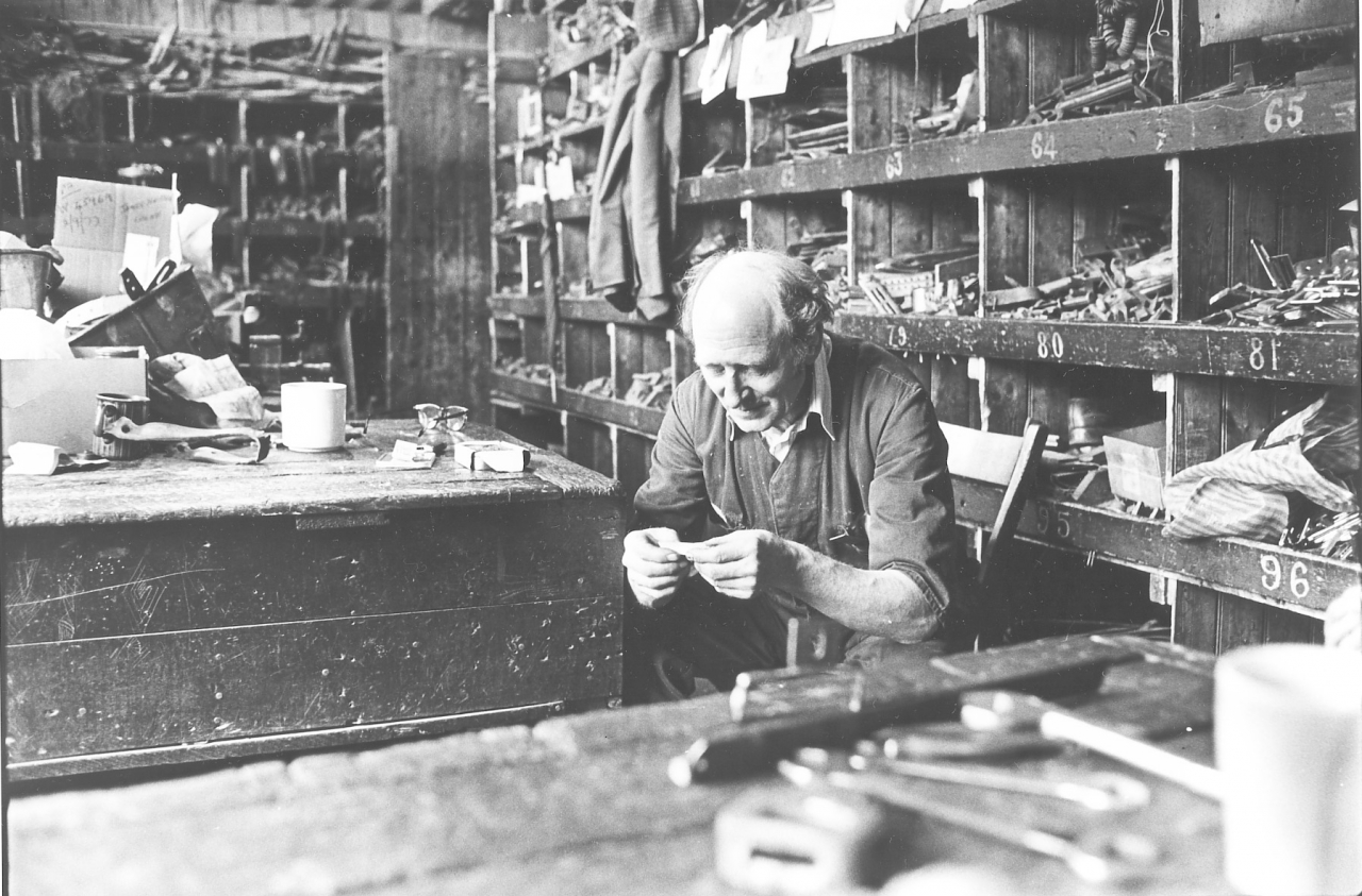
Bancroft folio, tackling picture number 34. Negative number 7720324.
This is the start of one of my favourite sets of pictures, about one of my favourite people actually, Mr Ernie Roberts. Picture 34 is of Ernie Roberts sat in the tacklers store in the warehouse rolling a cigarette.
I shan't go into too much detail about Ernie apart from the fact that I think that he, in common with people like Mary Wilkin and Jim Pollard, are the salt of the earth. (He has his own set of transcripts) He has seen the lot. He fought for this country in the war, he's seen bad times, he was brought up in terrible poverty, in fact he is bow-legged with rickets. But he had an unquenchable sense of humour and all told he is what I would describe as a complete man. Ernie Roberts was definitely a man and I have a lot of time for him.
What we are going to do now is follow Ernie as he deals with our friend the polyzone warp which we left with James upstairs, sat on the floor waiting for the attention of the tackler.
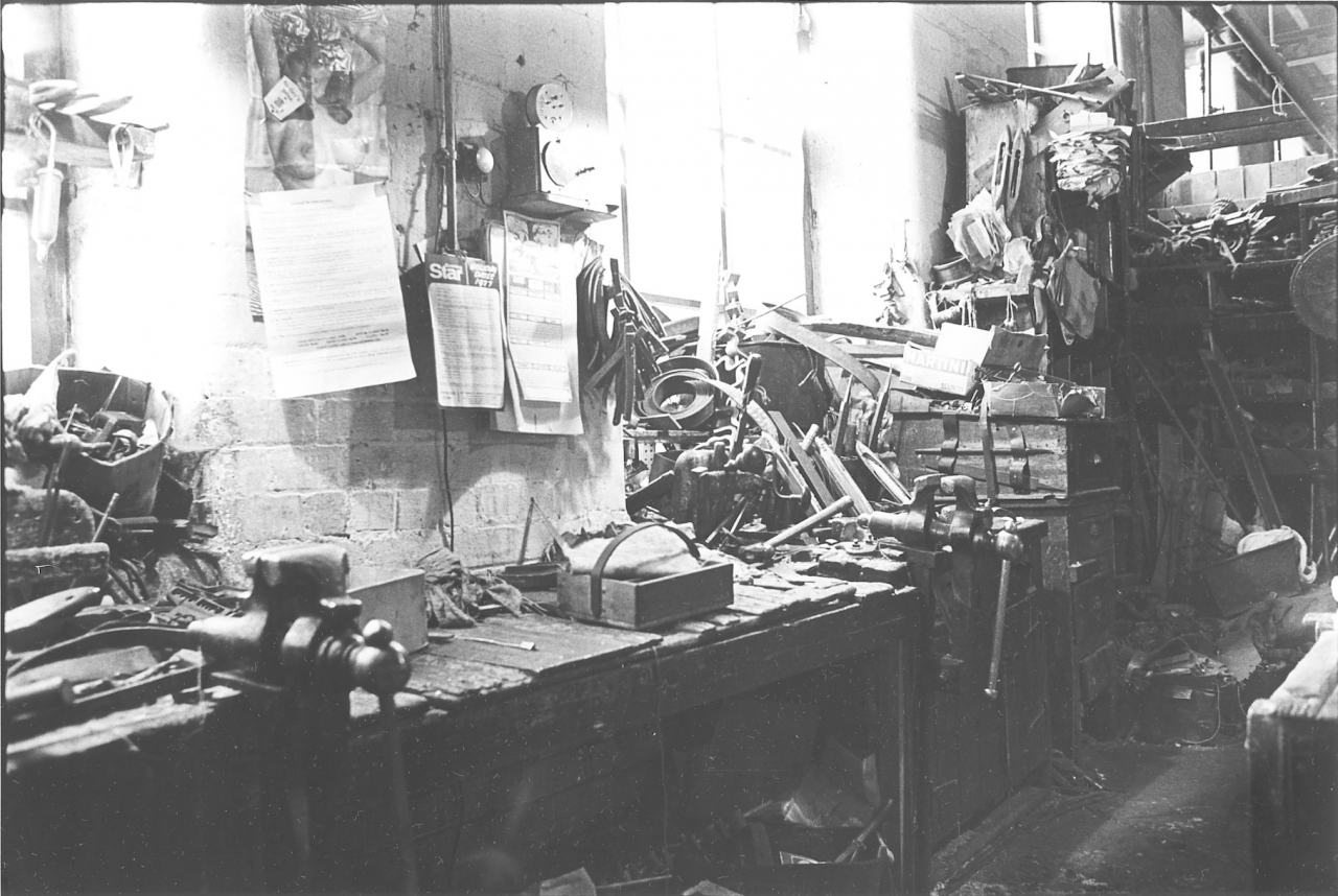
Picture number 35. Negative number 7720321.
Just before we go upstairs let us look at another picture of the general confusion in the tacklers store, picture 35. As Ernie says, at one time in the old days under the strict regime that went on then and a keen boss tackler this place would he spotless. Everything would be in its own place. Attrition over the years has meant that everything has quietly broken down, nothing's ever been replaced or even swept up in some cases. We have reached the situation that you can see there where stuff seems to just be piled haphazard all over the place. Strangely enough the tacklers knew exactly where everything was and it was very seldom you saw them hunting round for something. They knew where things were and the job went on well.
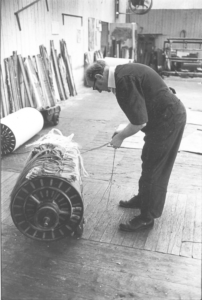
Picture number 36. Negative number 7720012.
Here is Ernie up in the preparation floor. He has lifted the warp on to his bogey and is straightening up the bands that are attached to the bottoms of the healds and will be attached to the lambing wires in the loom. He slackens all of them off before he goes down so that they are ready for being attached and tightened up. He is also making sure that the strings are all right and that the eyes are firmly fixed in the heald staves. If any repairs or alterations need doing to those he will get them done up here before he takes it down into the shed. You’ll notice he has got that warp on his truck, on the tackler's truck, that essential part of his equipment.
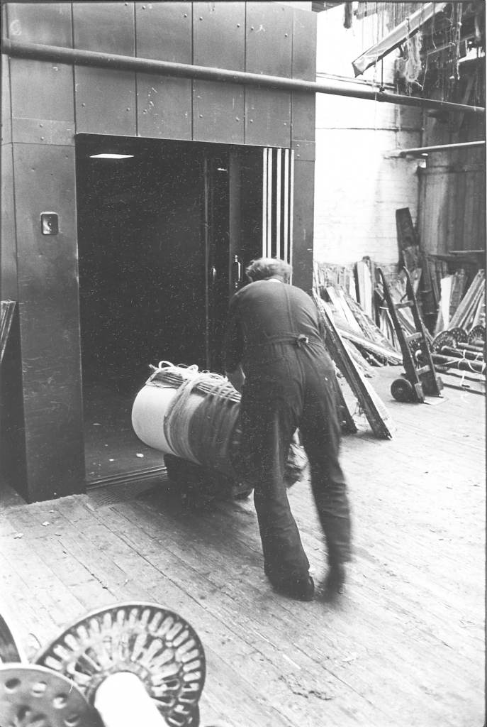
Picture number 37. Negative number 7720014.
Here we see him disappearing at a tremendous rate of speed considering his little bow legs into the hoist ready to go down into the warehouse and thence into the shed.
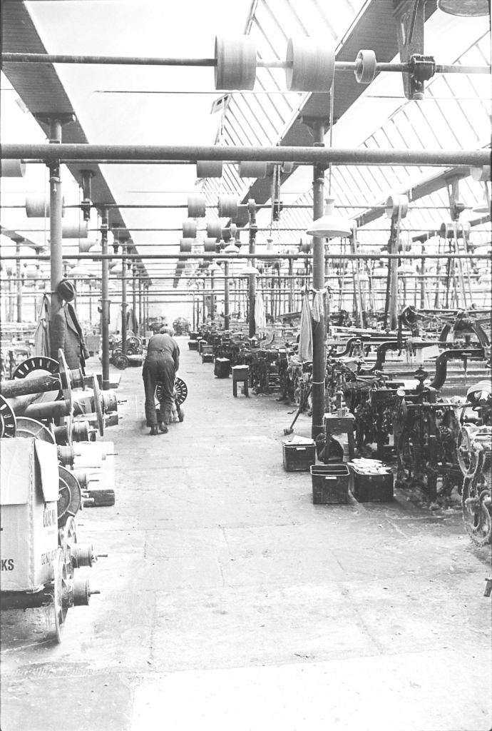
Picture number 38. Negative number 7720015.
Here we have Ernie, still moving at a fair speed up the [broad] alley in the weaving shed. That picture tells you a lot about the state of our shed. Look at that floor, it was terrible. In some places it was almost impossible to wheel a warp, they'd fall off the truck if you didn't watch it.
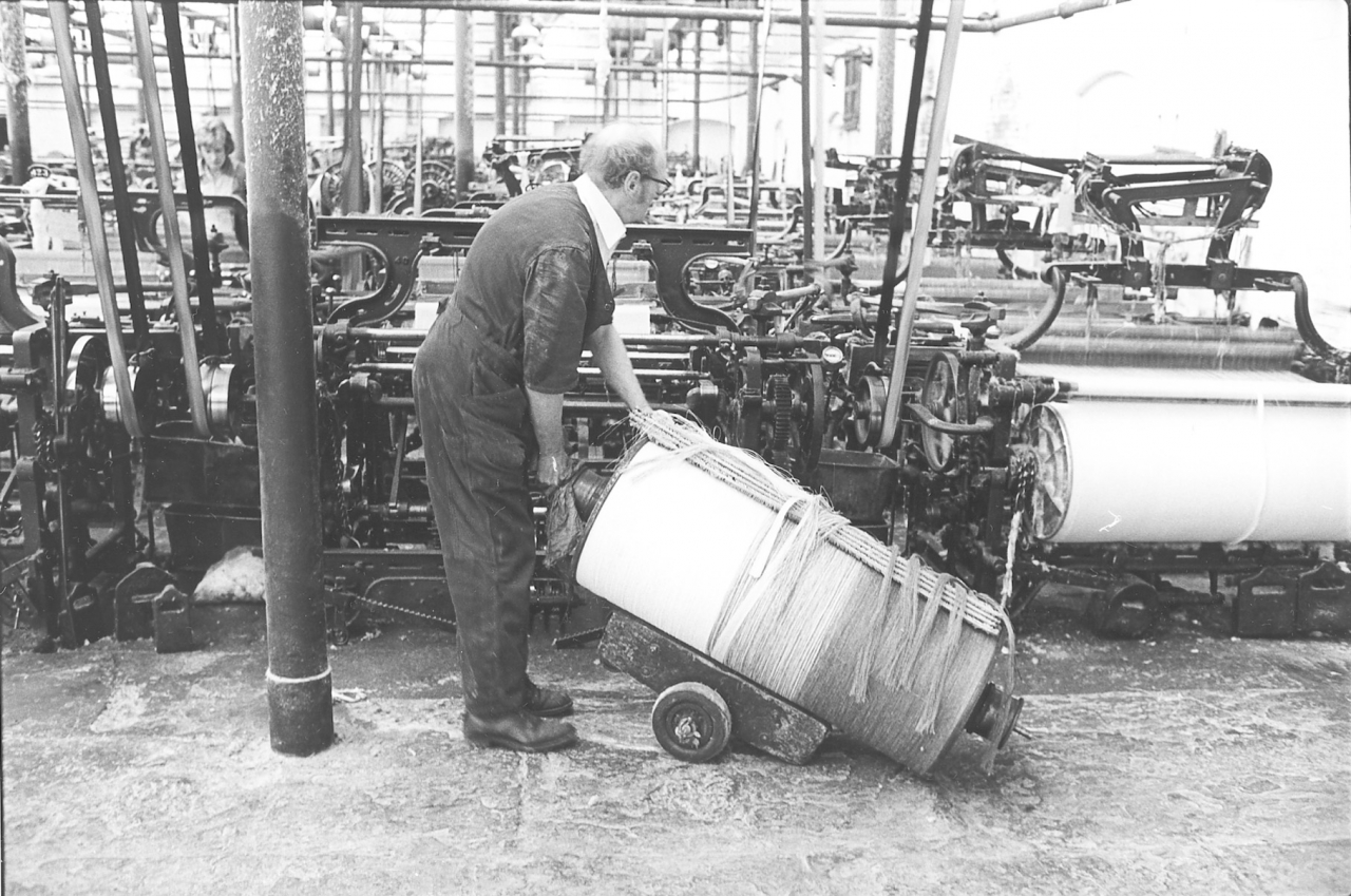
Picture number 39. Negative number 7720016.
Here Ernie has arrived at the back of his weaver’s loom into which he is going to install the warp. This process is known as gaiting a loom. Notice that in this case there in a big space at the back of this loom. This wouldn’t normally be the case, Ernie would he working in a very narrow alley but in order to make things better for myself, easier to photograph, I picked a warp that was going into a loom that was going to be fairly easy to get at. In point of fact this is at the back of the shed on the south side where a lot of looms have been taken out. There was an empty space at the back because Bancroft shed was not full up at this time. There were only about 500 looms in it and there was room for about 850 at this spacing.
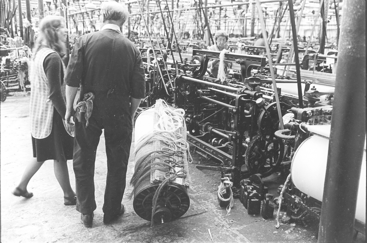
Picture number 40. Negative number 7720017.
This is something that very often happens to a tackler. One of his weavers has come to have a word with him, in this case a particularly young weaver, Susan Longbottom. We were at this time trying to get a few younger girls in but I am afraid that it was done in a very half hearted fashion and never really came to anything. Susan left once we had trained her and went to work at Johnsons in Earby but she wasn't as happy there as she was at Bancroft.
That was one of the things about Bancroft, everybody seemed to he happy working there even though the conditions were so terrible in many ways. Ernie said that Susan would make a good weaver because she was there for the money. This was the only incentive to come and says volumes for the combined effects of high unemployment and low wages in the area unless you were lucky enough to get into Rolls Royce.
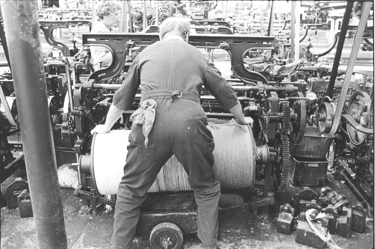
Picture number 41. Negative number 7720018.
This is a typical tackler’s stance. Ernie is manoeuvring the right hand pike of the beam into the bearing surface in the loom. This is an awkward lift as he is too far back because of the warp and the bogey. Almost all tacklers were ruptured at some time in their lives for this reason. Remember that this would be much worse if it was a narrow alley.
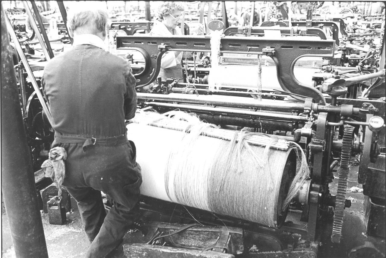
Picture number 42. negative number 7720019.
Here you see Ernie lifting the left hand side of the warp in.
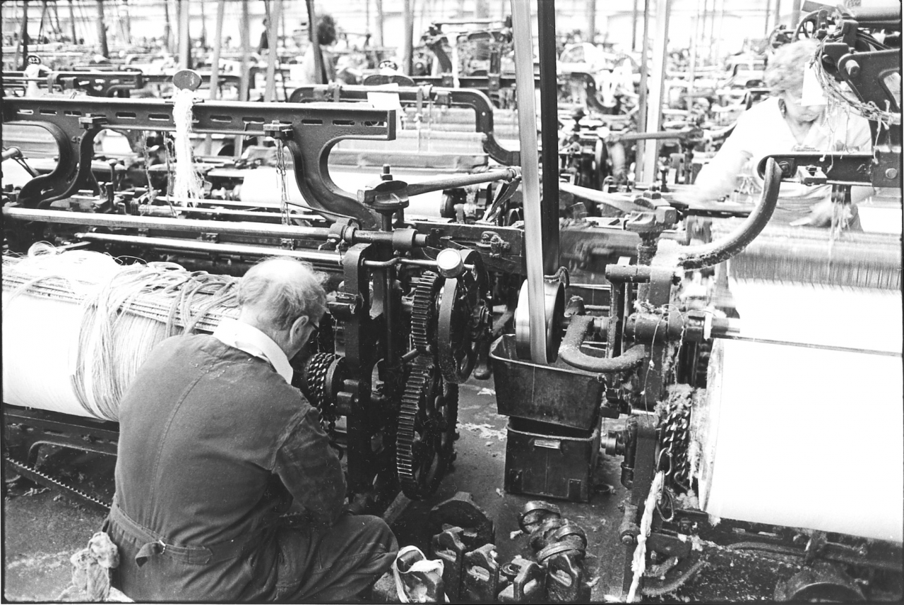
Picture number 43. Negative number 7720021.
Here he is putting the chains on to the boss on the end of the beam that was used upstairs for the driving chain on the tape. These chains act as a brake on the warp and allow the cloth motion at the front of the loom to exert tension on the warp. These chains go down on to the levers at the bottom, and then weights are hung on the end of the levers.
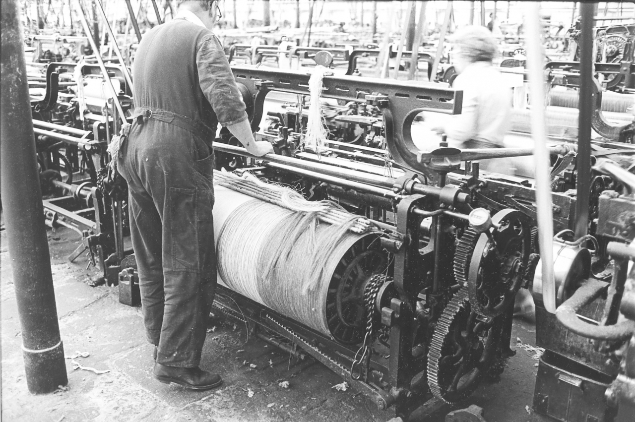
Picture number 44. Negative number 7720022.
This gives a good view of the levers and the chains. The other side is exactly the same. The chain isn’t on the lever here because Ernie needs the warp to stay free for the moment but you can see that when it is attached to the lever and weights are hung on the chain will have considerable tension on it and be a powerful brake. Ernie is just moving the rocking rail on the back of the loom and will put it in place on the trunnions that can be seen level with the top of the warp.
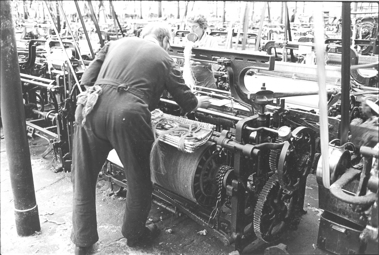
Picture number 45. Negative number 7720023.
Here Ernie is reaching through and putting the warp card on to the breast beam of the loom on the weaver’s side. He has taken the band off the warp that was holding the healds and reed secure.
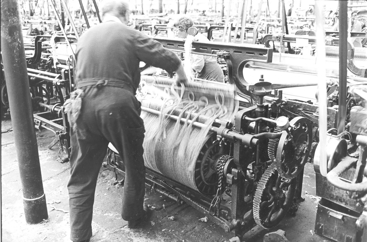
Picture number 46. Negative number 7720024.
Ernie is passing the healds and reeds through the loom. Notice that he has threaded them through the double bars of the rocking rail and he will lay the assembly down in the middle of the loom where he can reach it when he has got everything ready at the weaver’s side.
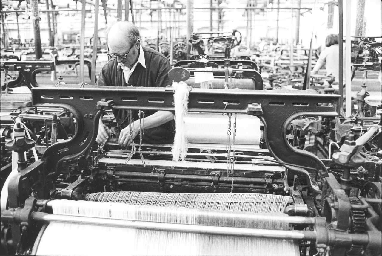
Picture number 47. Negative number 7720029.
Here he has moved round to the other side of the loom. You’ll see his healds and reeds are just resting on the crankshaft inside the loom. What he is actually doing there, he is taking off the temple caps ready for putting the warp through. Notice that the top strings for the healds are already in place on the loom. These are never removed because once set they don’t need altering and they are a good fixed point for the tackler to start from when adjusting the height of his healds.
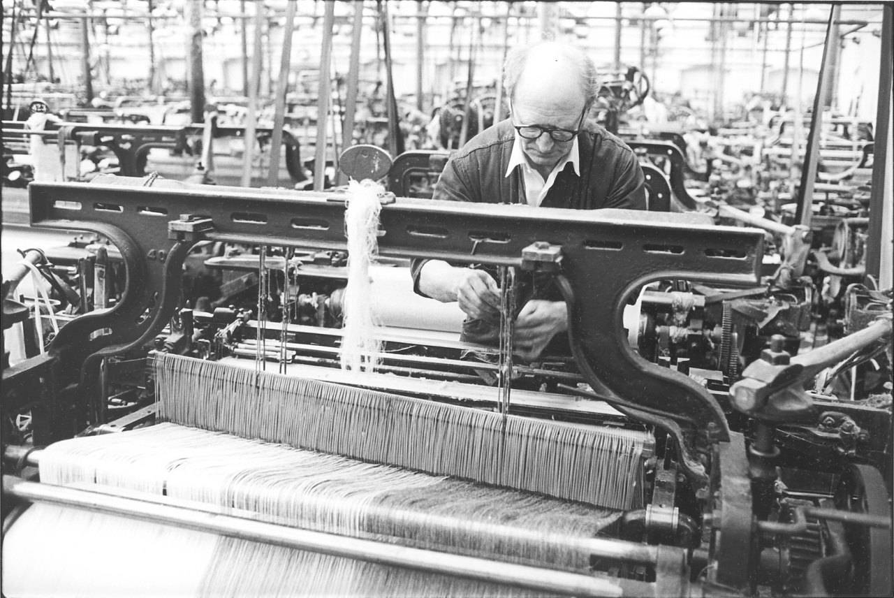
Picture number 48. Negative number 7720028.
Here Ernie is attaching the strings on the loom to the top heald staves. This connects the healds to the lifting mechanism on the top bar of the loom. On this loom this is a single shaft. Ernie and Jim Pollard explain these at great length in their own contributions.
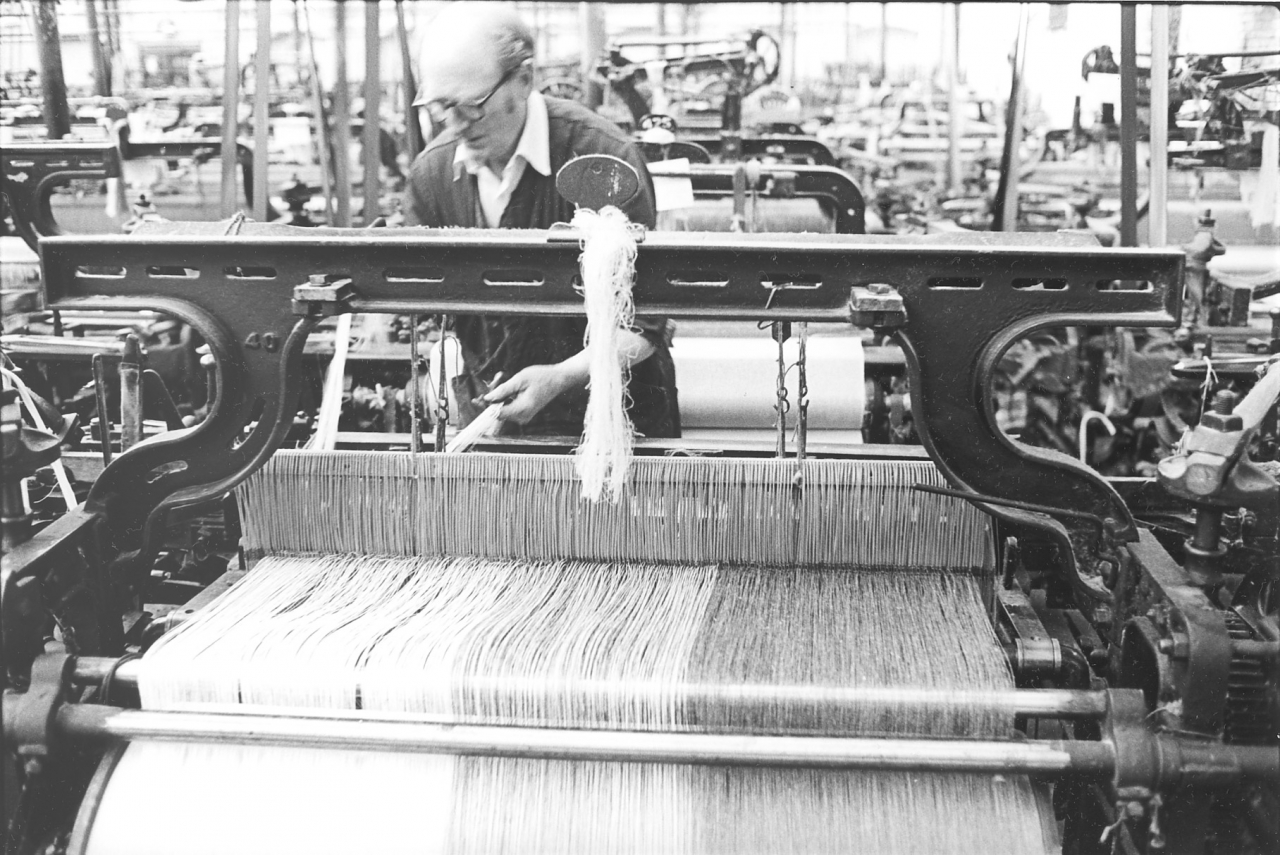
Picture number 49. Negative number 7720026.
Ernie has his healds hung up and he is drawing out his ends over the breast beam of the loom in preparation for forming his shed and completing the gaiting.
Picture number 50. Negative number 7720030.
In this picture taken from the front of the loom Ernie is still unfastening the knots in the lease of the warp and draping them over the breast beam. Notice that the reed is still fast in the spare ends of the healds where Jim trapped it upstairs.
Picture number 51. Negative number 7720033.
Ernie has brought the reed forward and placed it in position on the slay. It is now in the position where it will be when the loom starts to weave.
Picture number 510. Negative number 78107731.
The change in numbering here is because I had to insert the following pictures at a later date. When I was doing the original pictures the engine was running and I had to get back to it. I had pushed my luck by staying away so long. I waited until Ernie was gaiting a polyzone warp on the same weaver’s set of looms and finished the covering of gaiting in that way. The main difference is that the loom Ernie was working on in the first phase of coverage was a right handed loom. On this loom the knocking on lever is at the left hand side but the loom is otherwise identical apart from one quite important detail. On the previous loom Ernie slotted the reed into the slay before the hand shelf went on. On this loom he has not done this. He will put the reed in place in a different way. I think this is because this loom was what they call a fast reed but I’m not sure. In the picture Ernie is trapping the ends of the warp between the top roller, the sand roller and the cloth roller below. The sand roller is covered with either coarse sandpaper of a strip of metal perforated like a nutmeg grater. This roller grips the cloth and pulls it through the loom against the resistance of the loom weights and chains. In this case, and until there is sufficient cloth to replace this, it is the warp that is gripped. Notice that he is using his ruler, it’s one of the few things, apart from stirring tea, that a tackler uses his ruler for, pushing these ends into that gap. It's a very critical operation because it's essential that all these ends should have an even tension on them.
Picture number 511. Negative number 7810731.
Once all the warp ends are trapped in the sand roller Ernie ties a band across and then winds a couple of turns round the sand roller by hand. Recognise that normally the cloth winds on the cloth roller but while he is starting the loom he winds the warp on to the sand roller. Only when he has woven enough does Ernie wind this all back and attach the cloth to the cloth roller. At this point the weaver takes over the loom.
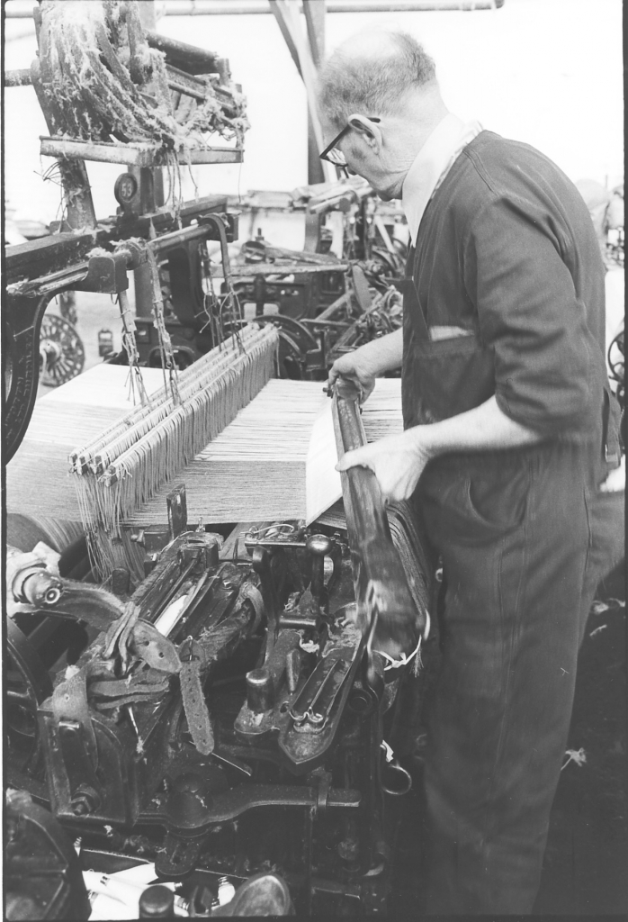
Picture number 512. negative number 7810631.
Here Ernie has drawn the reed forward, and is slipping the slot in the hand shelf over it . This is a fast reed loom, once the reed is in the hand shelf it is held solid.
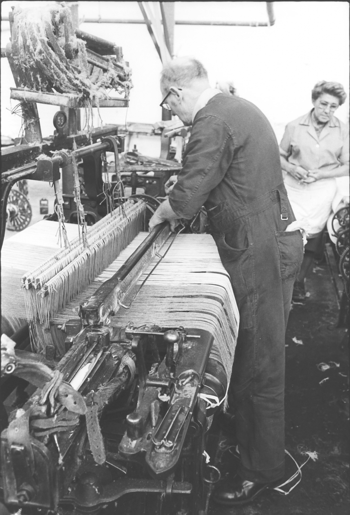
Picture number 513. Negative number 7810633.
Here Ernie is fitting the hand shelf and reed into the slay.
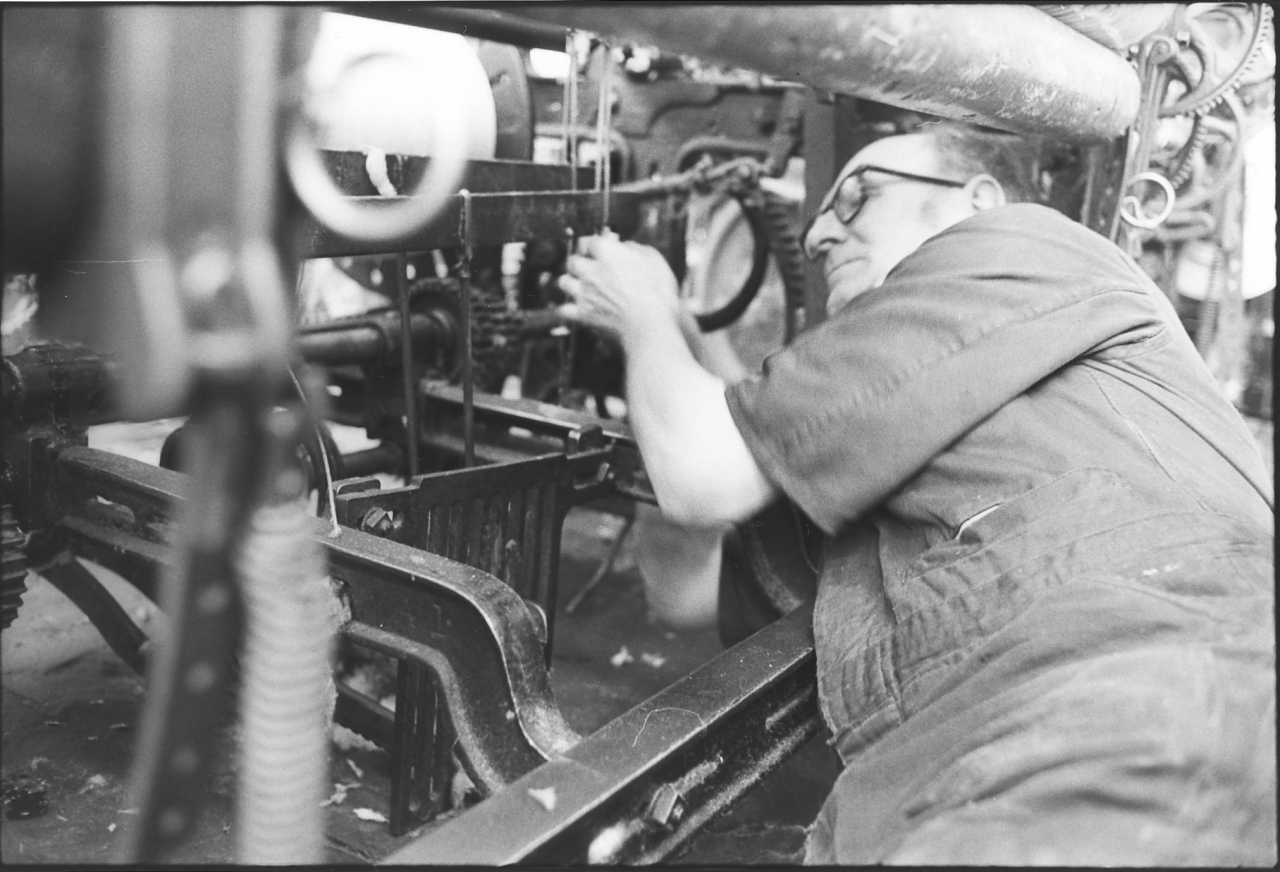
Picture number 514. negative number 7810921.
Ernie is under the loom now attaching the bottom strings from the healds to the lambing wires on the motion under the loom. The lambing wires are the rods which run down to the shedding motion underneath the loom, the tappets.
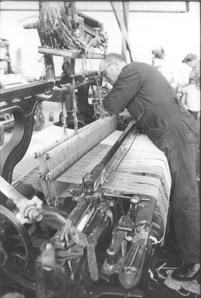
Picture number 515. Negative number 7810602.
Here Ernie is putting the rods through behind the healds which are tied in place and help to give the shedding of the loom. He puts these in in the different sheets controlled by the healds and they help to form the shed of the loom while it's running. Notice his foot is on a lump of waste on the floor. This is what he used to cushion his hip bone when he was on the floor dealing with the shedding motion. A tackler of Ernie’s experience always puts a bit of something warm on the floor to protect himself.
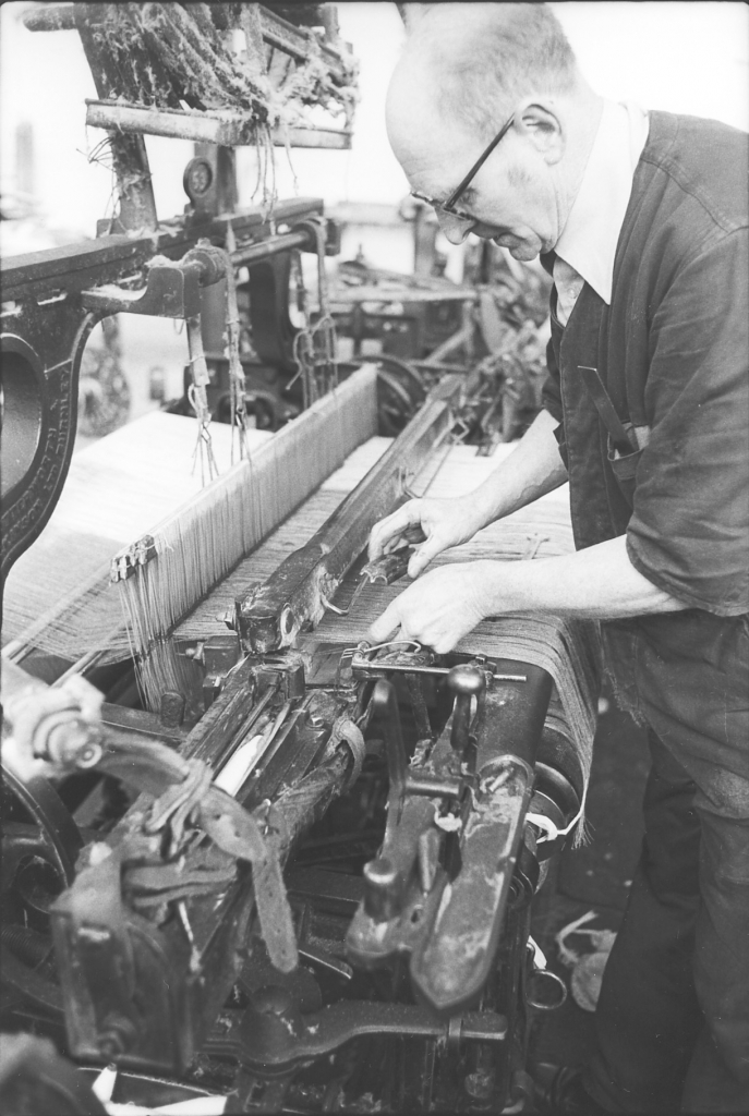
Picture number 516. Negative number 7810608.
Now the reed is in it’s correct place Ernie can replace the temple caps. He knows the warp is in the correct place because there has been no weaving and hence no contraction. The stud that will fix it in place is in the shuttle stand by his left hand.
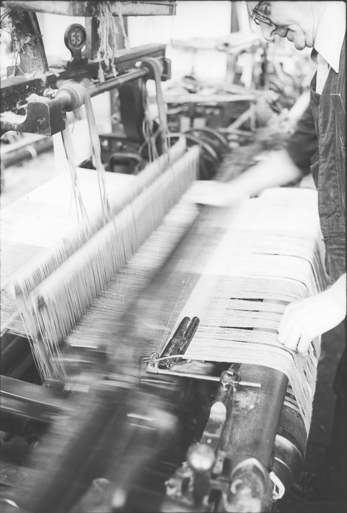
Picture number 517. Negative number 7810841.
This is a nice picture of a loom running and you can actually see the weft across the shed before the reed beats it up. Ernie weaves about three feet of cloth and then stops the loom and winds all the fag end of the warp off the sand roller. He can then cut the cloth off straight and replace it in the correct place, on the cloth roller and trapped by the sand roller. From here on the weaver is in charge, she can start earning money again.
The whole process of gaiting a loom, if all goes well, takes about a quarter of an hour. It looks simple on these pictures but there is a lot of skill embedded in the process. I’ve asked Ernie about this but these small wrinkles are so ingrained in him by experience that he can’t tell you what they are.
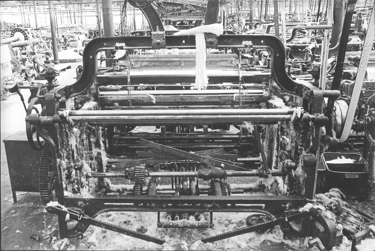
Picture number 52. Negative number 7718037.
This is an overall picture of a Lancashire loom, empty and ready for the sweeper. Usually these looms were swept by the sweeper when they were empty because that was the time when they were easiest to get at. However, this wasn’t always the case as we shall see in later pictures.
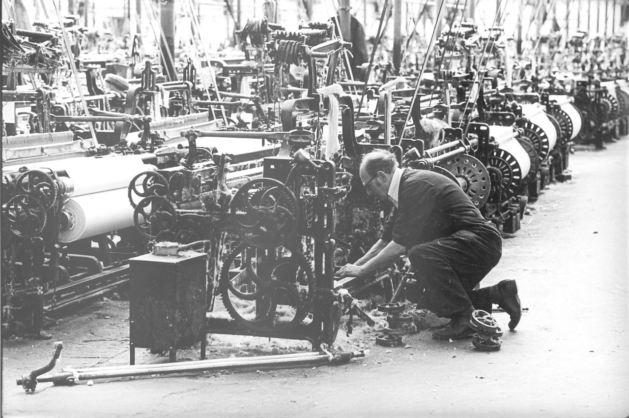
Picture number 53. Negative number 7717714.
This is a typical picture of a tackler at work on a loom in the shed. Ernie is changing this loom over from one cloth to another. He is changing the tappets.
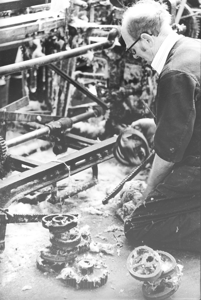
Picture number 54. Negative number 7717710.
I think he is putting this loom on to a single rose wheel. These are the rose wheels that he has here on the floor. This is the set of rose wheels for this loom. There are four rose wheels on one, three an another and the one he has in his hand just has two and I think he in putting that one back on.
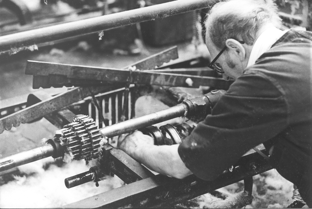
Picture number 55. Negative number 7717709.
Here he is fitting the ordinary double tappet, this is for a plain cloth.
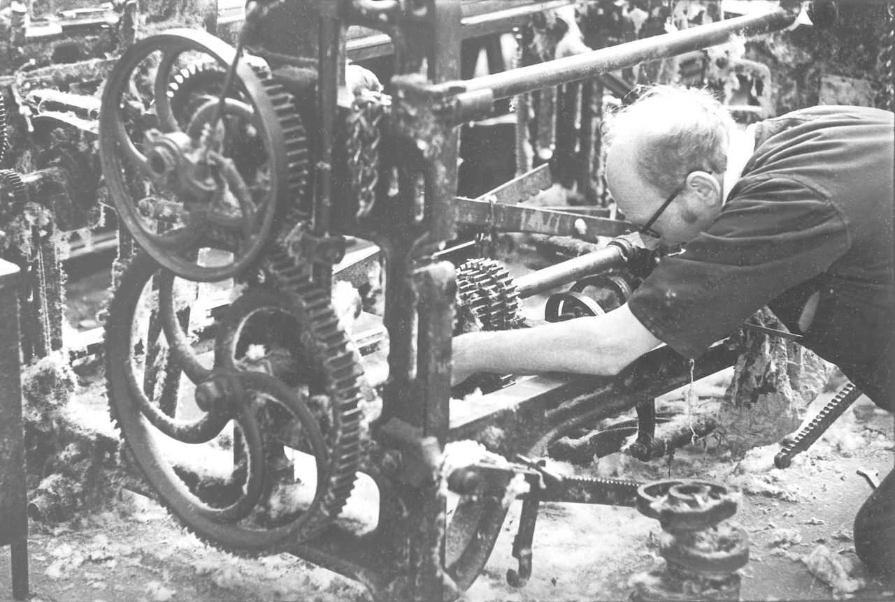
Picture number 56. Negative number 7717713.
Ernie is still fitting the rose wheel. He’s fitting the correct driving gear on to the shaft on which the wheels are fitted. Lots of information about loom construction in these pictures.
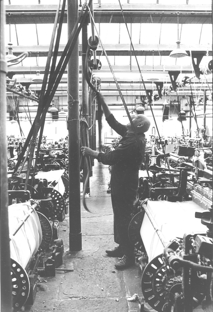
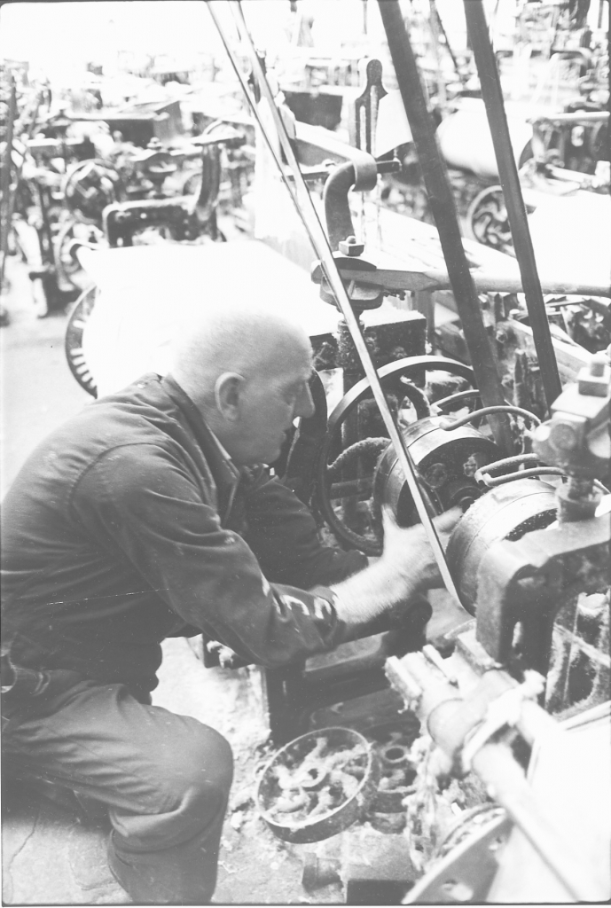
Picture number 57/58. Negative numbers 782106/08.
Here’s are two unique pictures for you. This is Fred Inman who was 76 at the time putting a belt up in the shed while the mill was stopped at dinner time. Tacklers used to do this while the shed was running. It's obviously a very dangerous thing to do and it always surprised me that tacklers were prepared to do it but this dates back to the days when tacklers were paid on the amount of cloth that the weavers got off the looms and rather than leave a loom stopped all through one period of running of the engine if a belt broke they’d repair it and put it up while the engine was running to keep their own wages up. This has hung on in the trade and a lot of tacklers will still put a belt up when the shed's running, when the engine’s running. When Fred did this he was putting it up with the engine stopped but the method's just the same. You just take hold of the belt, form a loop and flick a loop up so that it drops over the pulley. It’s not easy but when I tried it I found that you could soon get the knack with a bit of practice. When you have put it on to the shaft pulley it doesn’t drive until tension is put on so you can position it on the driven pulley and as you push it on with the flat of your hand the tension kicks in the belt starts to drive the pulley and throws itself on. This is on to the loose pulley, it is always the outside pulley so that this can be done while the shaft is moving. Once it starts, get your fingers out sharpish!
DESCRIPTION OF LOOMSWEEPER PICTURES IN THE BANCROFT FOLIO.
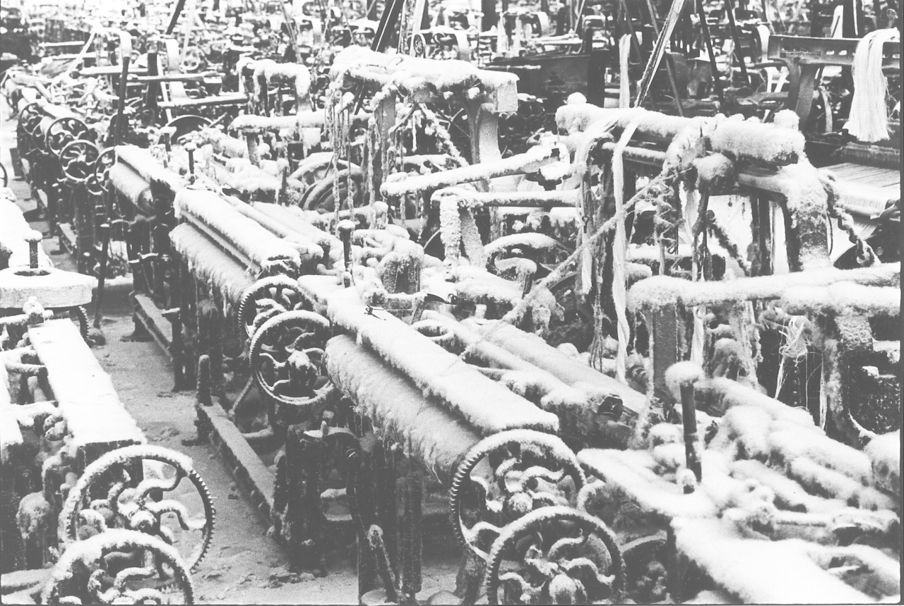
Bancroft folio, loomsweeper picture number 59. Negative number 7717430.
This is a very sad picture, something which was quite common in the shed at this time. These are stopped looms gathering dust and dawn and gradually looking like a snow scene. This picture encapsulates the problems of the industry. I’ve seen weavers who had a set of looms like this next to them go and sweep them because they couldn’t bear to look at them all day. A very depressing sight.
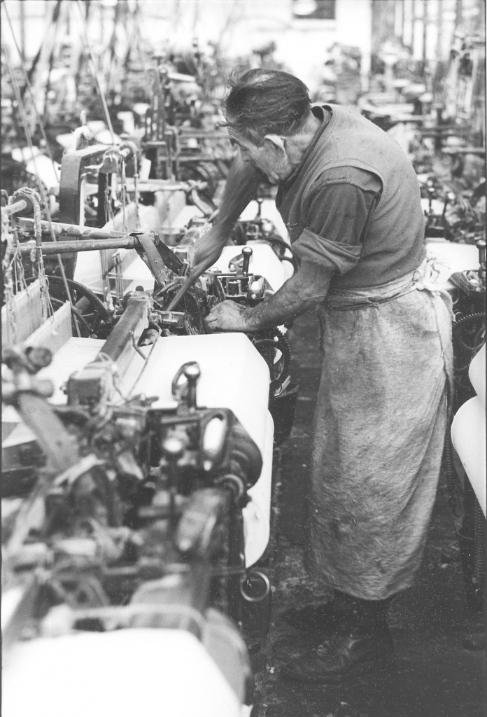
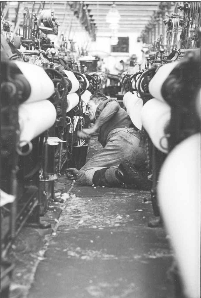
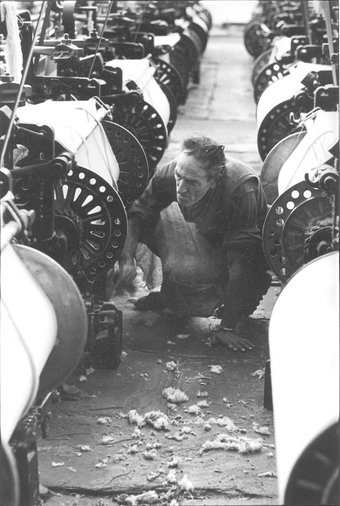
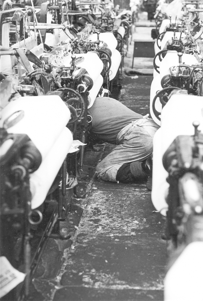
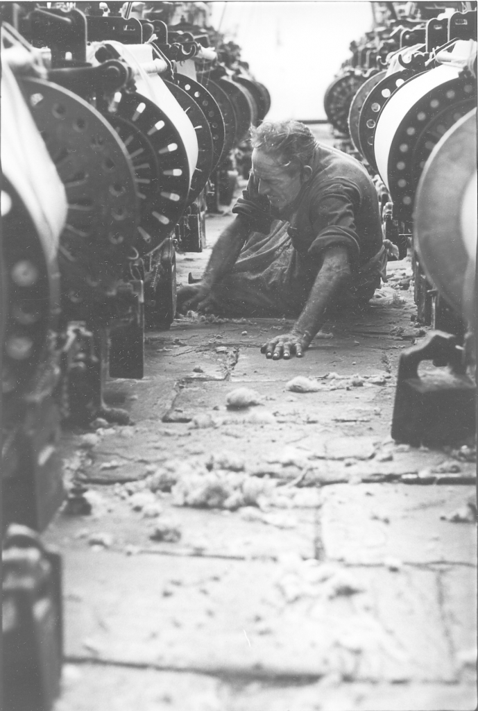
Picture number 60/61/62/63/64. Negative numbers 781128/33/39/31/07.
This is a series of pictures of ‘Paraffin' Jack Grayson. His job was to sweep looms all day. I think they had about 140 looms a week to sweep and we had three sweepers when we were lucky. Regarded in the mill as the lowest form of life but even so a very skilled and essential job. Anyone who doesn’t believe this should try doing it. Jack could sweep five looms while you were doing one. Jack was a good sweeper but had some peculiar ways. He used to take the top strings off the looms which annoyed the tacklers no end. But apart from that a good man at his job. Jack came to a bad end. He lived alone and had a lot of cats. He collapsed and died and before he was found his cats had started eating him. What a sad end.
DESCRIPTION OF THE CUTLOOKER PICTURES IN THE BANCROFT FOLIO.
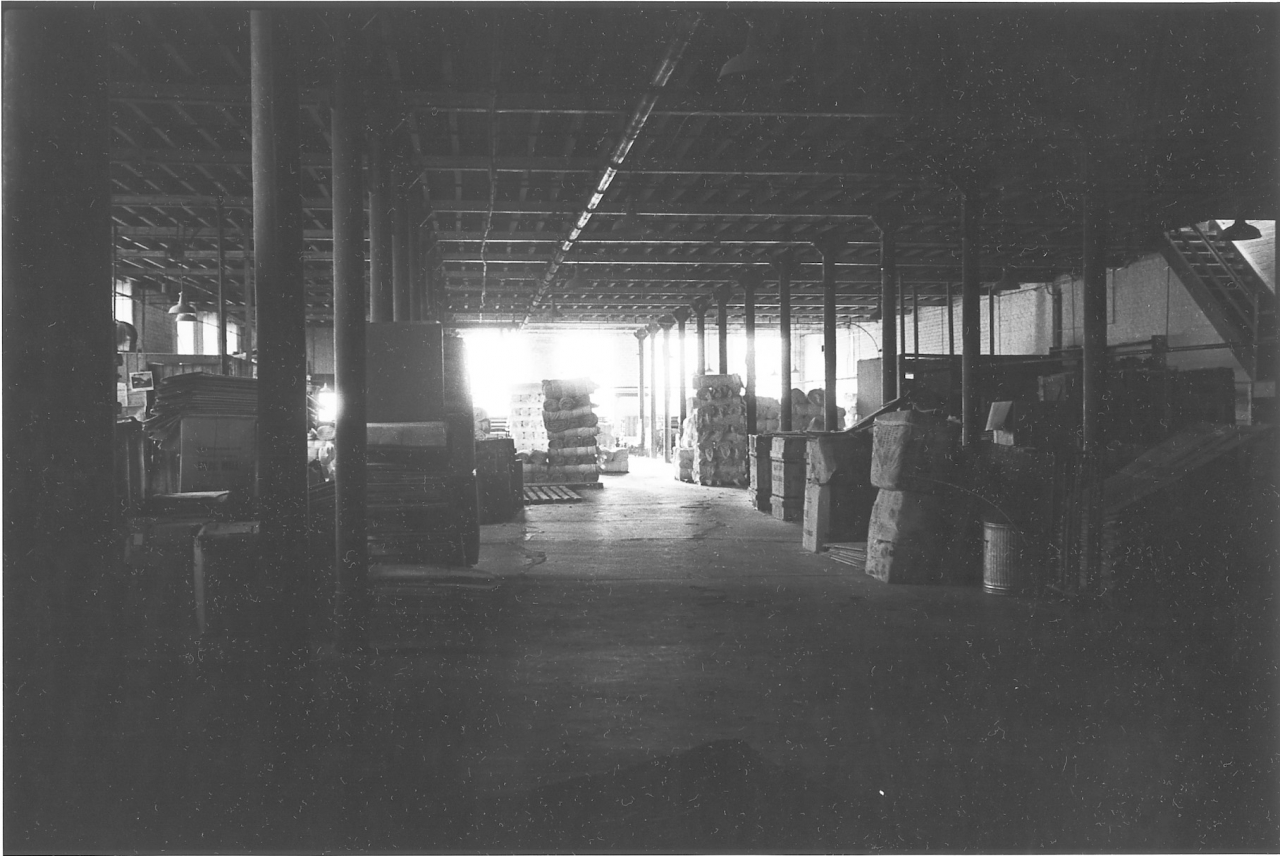
Bancroft folio, cutlooker picture number 65. Negative number 770411.
This a view up the warehouse from the engine house end. A dark, gloomy place, stacked up with boxes, piles of cloth, anything that nobody could find any room for anywhere else was stacked up in the warehouse. There were boxes down there that hadn't been stirred for years and weren't stirred until the mill closed down and they all went out for scrap. Costly empties that should have gone back to spinning mills that had long since gone defunct. Iron pillars again, concrete floor and the main activities that went on there were storing yarn, storing cloth and at the top end, where the light was good, at the south end you see where the light's coming in through the windows were the cloth looking machines.
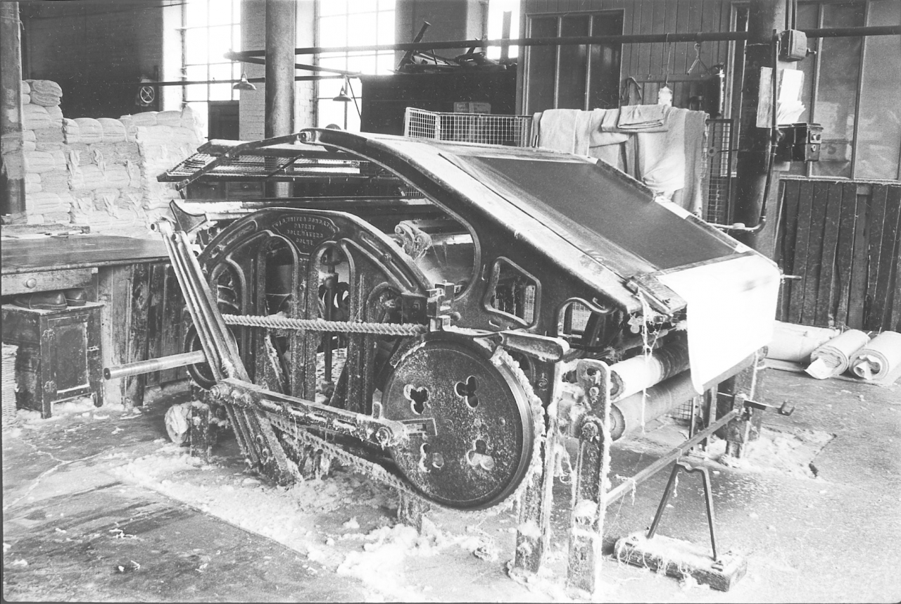
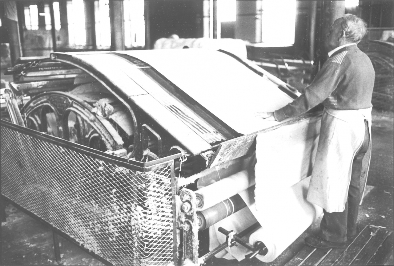
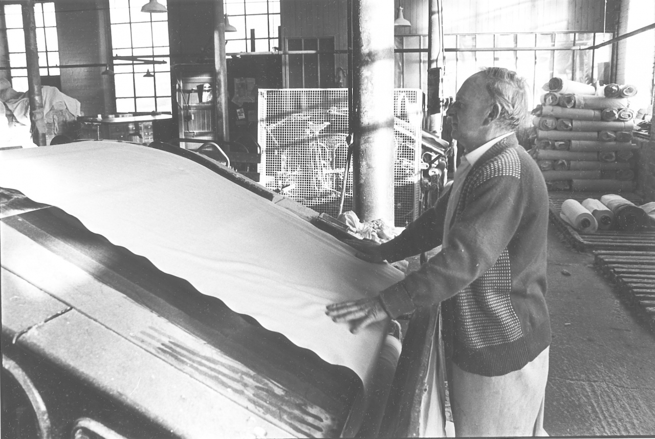
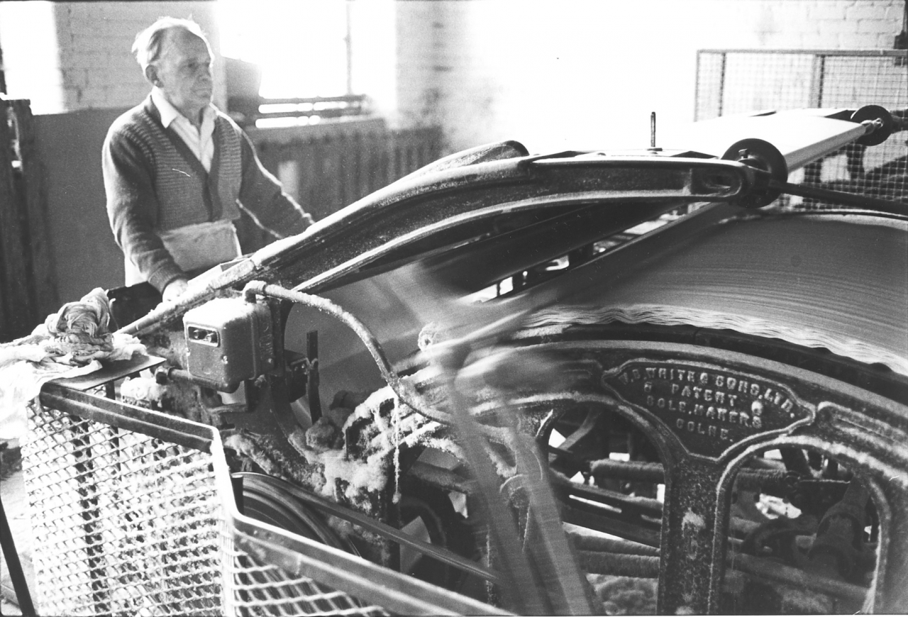
Pictures 66 to 73. Negative numbers 7718036/781003/7721817/781042/781008/7810111/781016/781019.
This series of pictures is of Fred Cope, one of our clothlookers or cutlookers, at work on his plaiting machine inspecting and measuring cloth and then bundling it up ready for dispatch to the customer.
On picture 67 you can see clearly how the cloth roller from the loom is mounted at the front. The cloth is led up over the table and is plaited or folded by the mechanism under the cloth table. As it passes over the table Fred is watching it for faults. If he finds any the weaver can be disciplined. However as weavers got more scarce they were given greater latitude. In the old days a clothlooker was a powerful man in the shed, he could cause you to lose your job or be fined. Those days are long gone and the constant complaint from management at the end was that the clothlookers were passing faults through.
On 69 you can see the plaiting mechanism working and the makers name, Whites of Colne who made looms as well.
On 70 Fred is taking the folded cloth out of the machine and in the next three pictures is bundling it on the table and tying it up. Notice how he has left a tag of cloth hung out of the middle of the bundle. This was marked with waterproof black crayon with the cloth type and length.
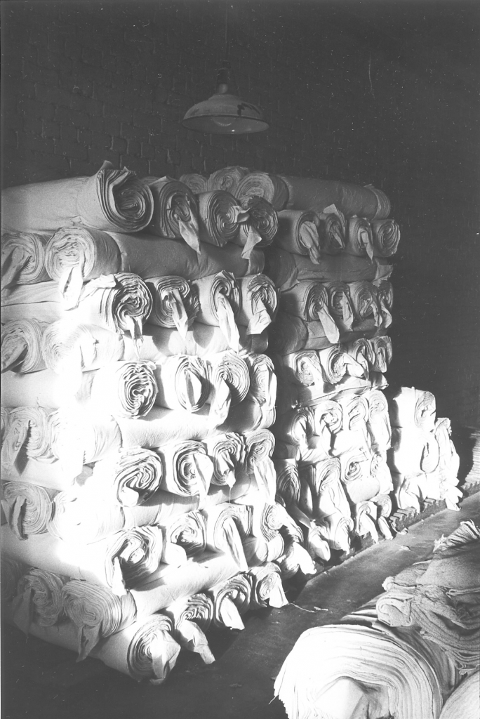
Picture number 74. Negative number 781019.
This is a nice picture of one of the piles of cloth waiting ready to go out to the finisher. This is not the same cloth that Fred was bundling up. This is a far better cloth, better and heavier cloth, you can see it's smaller rolls but typical of the way all the cloth in the warehouse was stacked up. The loose tag that hangs out at the end has the measurement written on it and so it's easy to reckon up what the cloth is.

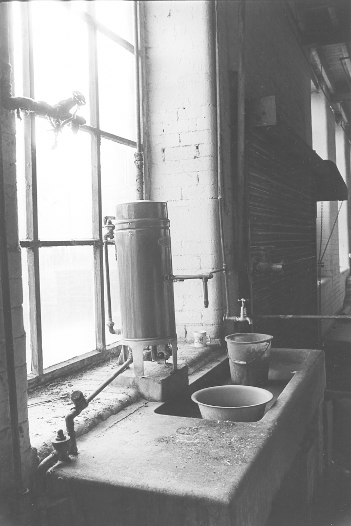
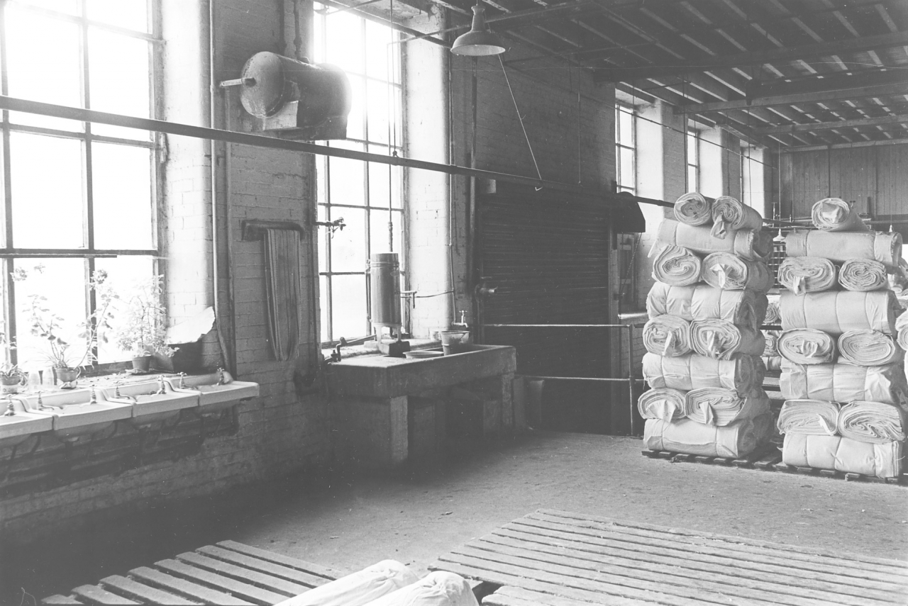
Picture number 75/76/77. Negative numbers 7718802/04/05.
The warehouse was also the place where the ablutions were. One washed ones hands in the warehouse and also kept ones cacti if one had a little garden. These here are Colin Macro’s, the roller carrier who was stone deaf and a bit of a character. He kept these cactus in the corner, and everybody used to get a bit of fun out of watching his cactus grow, he had quite a collection there at the finish and they seemed to do very well on the window cill in common with the tomato plants.
76 is actually the next window but one to the cactus garden and is the boiler for boiling water to make tea. It’s heated by steam from the boiler and everybody in the mill can go there any time they want and brew up. At one time some of the mills used to charge a penny a week for the use of this boiler and I worked it out once that with coal at about ten bob a ton, they were making more profit on the boiler than they were on a loom. It was just amazing, even at a penny a week it reckoned up if you had about 400 weavers in the place. Notice the big stone sink, beautiful stone sink, it really is a beautiful thing that. I don't know what will happen to that when they pull the mill down but I hope it doesn't get cracked up, it's too good.
77 is an overall picture of the end of the wash basins, part of Colin's garden, the hot water boiler and some cloth stacked up. Everything went on in the same place, there is no division, people brewed their tea up whilst looking at the cloth they had manufactured on the looms. I often used to wonder whether this wasn't part of the reason why Bancroft was such a satisfying place to work at. People could see the result of their labours and it wasn't regarded as being out of the way or abnormal to brew ones tea up next to a pile of the stuff that you have just made.
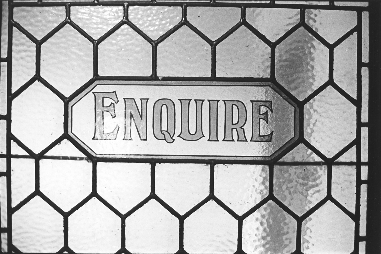
Picture number 78. Negative number 7721203.
In a strange way this picture of the window in the office which met you as you went in through the main office door into the lobby of the building where the offices were. I put that in because in many ways I think that picture typifies the mentality of the mill owners in the days when places like Bancroft were built. You'll notice that this sign doesn't say ‘Please enquire’ or ‘Knock and enquire’ it simply says ‘Enquire’. It might be just me but I can read a lot into the wording of that notice and of course the way it's done, in stained glass, in proper leaded lights in a mahogany frame. The whole of the offices are panelled in mahogany, beautiful.
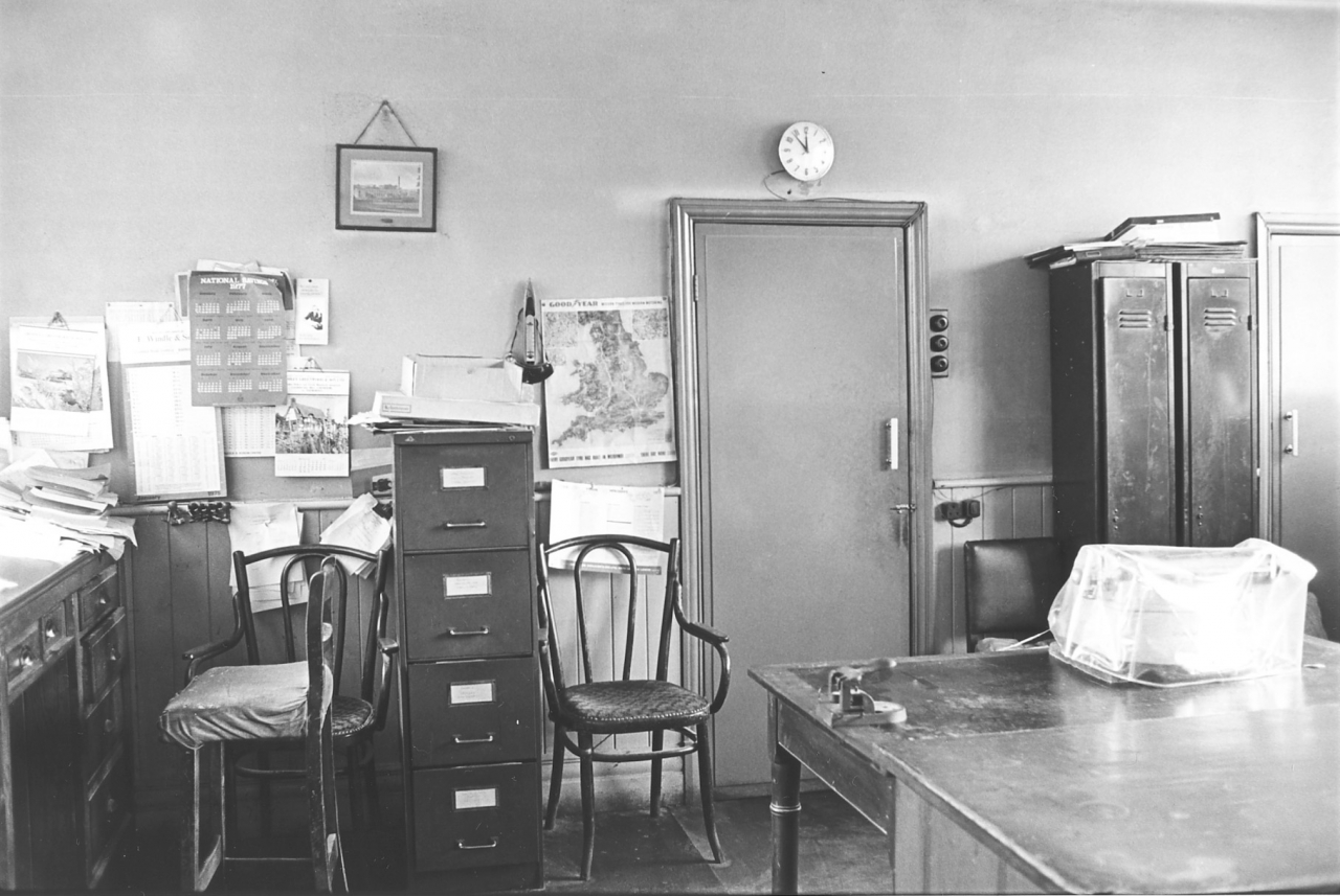
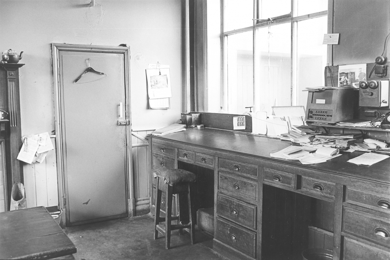
Picture number 79/80. Negative numbers 7718801/41.
Here we are in the office. This was the place where Sidney Nutter worked. Notice that in this office they were originally stand-up desks but somebody has brought in that foppish form of pandering to the bodily needs of the staff, the high stool. Not only that, but it’s padded and there’s foot rests as well. In the old days these desks were worked at standing up, there were no stools but the fact is that we got a bit softer at Bancroft between the wars and they started using stools. What can one say about things like that? This office was where it all went on, there was no more spent in the office than there was anywhere else.
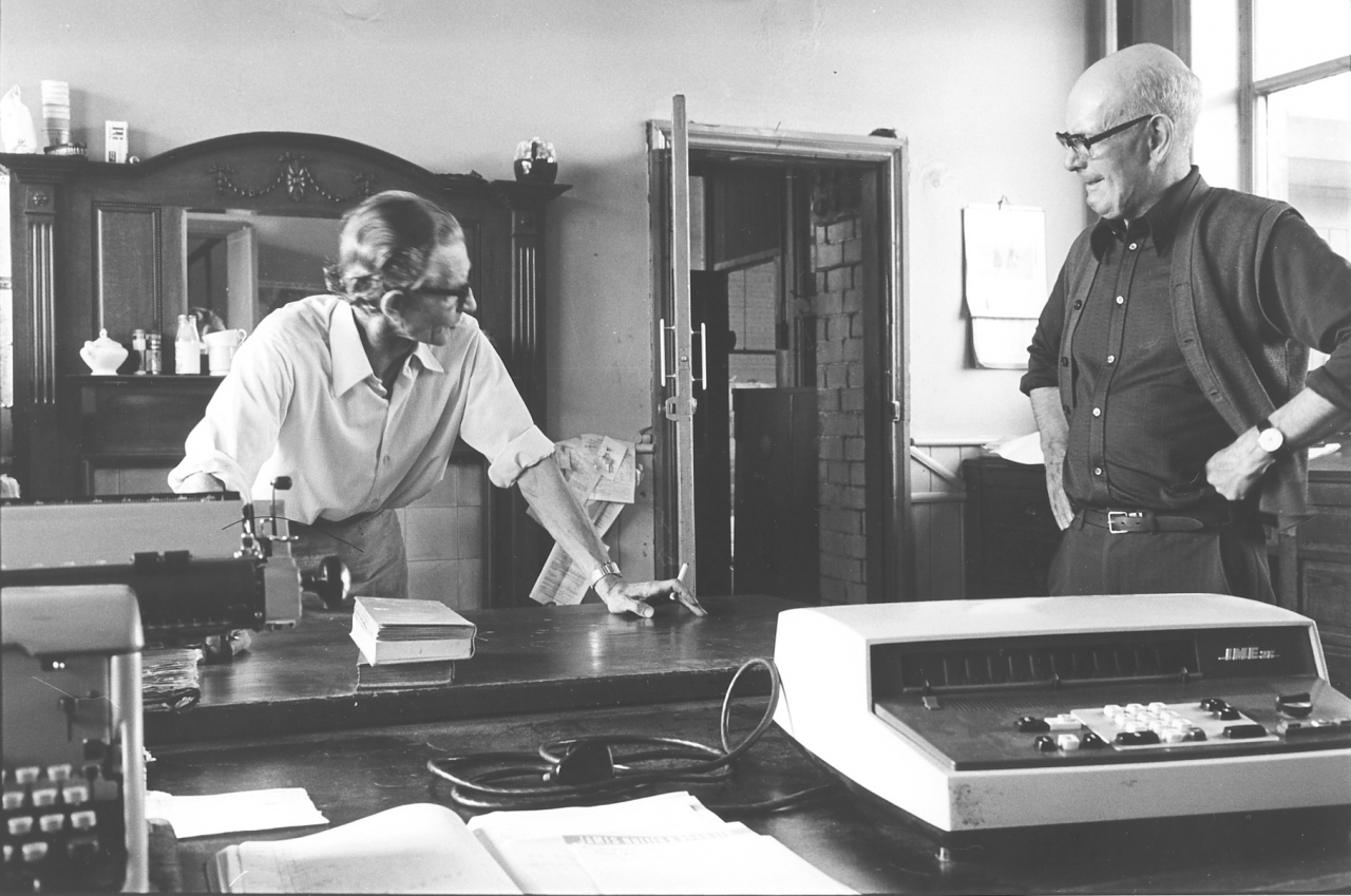
Picture number 81 shows Jim and Sidney Nutter in the office. Sidney was an amazing man, one of the original Nutter family but as he often said, not one of the Nutter millions. He ran that office single handed, he did everything, accounting, wages, invoices, dispatching cloth ordering yearn and coal. The only help he had was once a week when his cousin Ughtred Nutter used to come in and help make the wages up. The calculator on the desk is the one that used to drop the decimal point before I altered the voltage. Sidney got so despondent about the way things were running at the mill that he retired early and inside six months was dead suddenly of what seemed to be some form of brain tumour. It was a great loss for me because I had arranged to interview him and he was a goldmine.
Notice the fire surround behind them. There was an open fire in the office and on a cold day in winter they lit a fire. I asked one day why they did this and Sidney told me that the steam pipes had never been able to heat the office. All the engineers had tried but nobody had managed to improve it. Of course I saw this as a challenge! To cut a long story short, I turned the steam trap round on the end of the pipe so that it was fitted the correct way round and went back to the engine house. An hour later the intercom squawked at me and it was Sidney, he wanted me in the office. I went up and the temperature was about 85 degrees. They had all the doors and windows open and the fire damped down with tea leaves! I cracked the heat down and eventually fitted a restriction valve but the office heating problem was cured after 57 years.
I realise that stories like this will be looked at askance in 100 years time, I can hear researchers saying ‘He’s doing a bit of self-promotion here!’. Unfortunately not. The sad fact is that there were good engineers and bad engineers and Bancroft had had its share of the latter during its working life.
MISCELLANEOUS PICTURES IN THE BANCROFT FOLIO
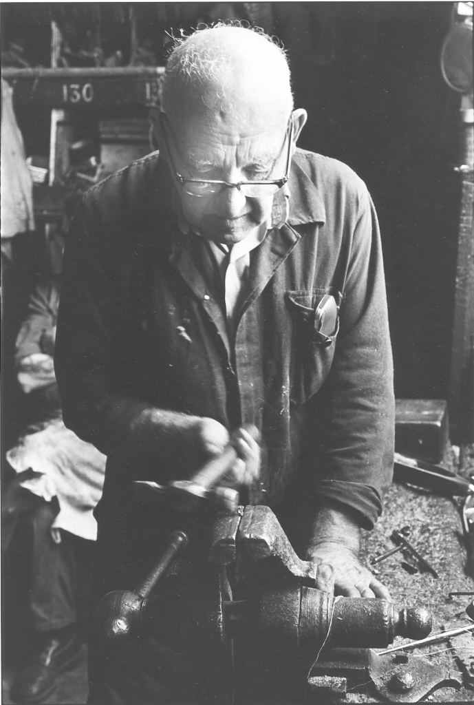
Bancroft folio, miscellaneous picture number 82. Negative number 785104.
There’s only one reason for this picture of Fred Inman. I like it and the man himself. As I re-transcribe these transcripts in September 2003 Fred is still alive and well and living in Earby. I rang him only two days ago to clarify a point about automatic weft stop mechanisms on automatic looms and he gave me the answer straight away. Fred is adjusting one of the clips which holds the shuttle peg in place in the weaver’s shuttle. It’s just a nice typical picture of a good man with enormous experience doing a skilled job with the minimum of tools. Fred has done extended interviews with me see 78/AH series and 2001/FI.
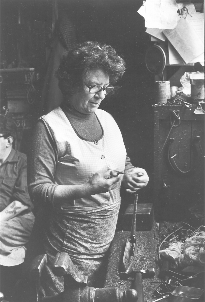
Picture number 83. Negative number 785134.
This is a picture of one of the weavers, Mary Cawdray, one of the old fashioned weavers and a really good one. She is cutting some fur and sticking it in her own shuttle. Typical old fashioned Lancashire weaver Mary, knows her own mind and isn’t afraid to tell anybody about it. I had a lot of time for her, a good weaver, not the fastest weaver, not the best weaver but a good steady weaver, always there, always weaving and very reliable. One interesting and telling fact about this picture is that the fur she is cutting up is from and old fur hat brought in by one of the weavers. Bancroft were too tight to buy any so the weavers brought bits of old fur in and I’ve known Ernie Roberts go to jumble sales to look for old fur off clothes and hats. You couldn’t make it up!
The tattooed arm you can just see behind Mary is Colin Macro the roller carrier that I was talking about that had the cactus garden. He used to spend quite a bit of time in the store roomy talking to the tacklers, or just sitting there with the tacklers because he had great difficulty talking to anybody because he was stone deaf but he used to spend quite a lot of time in there. The store room was a bit of a meeting place where all sorts of things both political and sexual were discussed This with the weavers as well, they were pretty broad minded lot, very down to earth and prone to good natured gossip. We had many a good laugh in there, usually connected with other people’s misadventures and failings. All part of the atmosphere of working at Bancroft. It was a good place to work, there's no doubt about it. I’ll be quite honest, I still haven't really reckoned up why.
SCG/23 September 2003
5,964 words.
LANCASHIRE TEXTILE PROJECT
TAPE 78/AI/11 (Side one)
THIS TAPE HAS BEEN RECORDED ON MAY 2nd 1979 AT 13 AVON DRIVE BARNOLDSWICK. THE INFORMANT IS STANLEY GRAHAM WHO WAS THE ENGINEER AT BANCROFT MILL AND WHO HAS BEEN THE INTERVIEWER ON MOST OF THE TAPES..
I am going on describing the pictures in the Bancroft Folio. We have now reached the section where I want to say quite a lot about the boiler because it isn’t described in any of the other interviews.
DESCRIPTION OF THE BOILER PICTURES IN THE BANCROFT FOLIO.
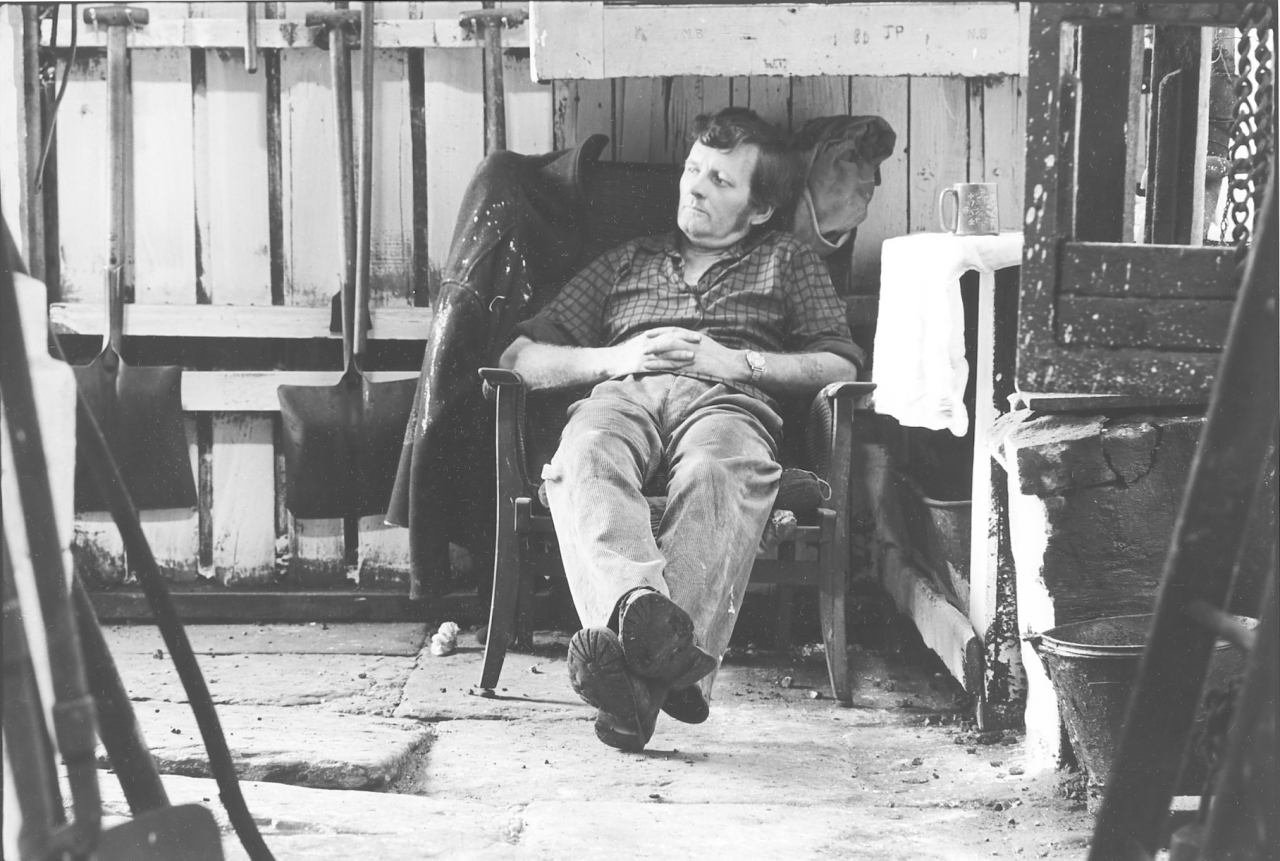
Bancroft folio, miscellaneous picture number 84. Negative number 7710124.
This in a picture of John Plummer the last firebeater or boilerman that I had. He was there with me until the mill closed. John had fired boilers all his life and used to entertain me with stories of carrying coal across the deck of an ice-covered trawler from the fish hold to the engine room while he was in a gale raging off Bear Island. He fired on Fyffe’s banana boats and said it was always worse on the way home when the refrigerating plant was eating steam. Occasionally, if the price collapsed they would stop the boat, open the hatches and throw all the bananas overboard and then turn round and steam back to the West Indies for another load. John was on the dole when I set him on. He had a large family and actually got less for working at Bancroft than he did whilst on benefit. This says quite a lot about the man. We got on well together and I enjoyed working with him. [2013. This is an understatement, he was the best working mate a man could have and an excellent firebeater. Many years later I got in contact with one of his sons and I told him what a good man his dad was. The son got back to me a few days later, John had been seriously ill in hospital but the lad had told him what I said and he was so pleased. He died the following day. I'm so glad that when he did, my opinion of him was fresh in his mind. Of course, I'm an old softie but that comforted me.]
Now I should explain that a boiler-man in Lancashire is generally referred to as a firebeater but you'll probably find that I call him a boiler-man or a firebeater or a stoker. I might call him by different names because anybody who has studied my history will realise that I am not a true Lancastrian and some words do come easier to the tongue than others.
This picture then is John Plummer sat in his chair in the boiler house and he is actually working hard there. Some people find this very hard to understand. Little story here, I’ve deliberately restrained myself from putting too many stories in but we’ll have a little one here that illustrates a point. I was asleep in the engine house one day, quite a usual thing to happen, the sound of the engine running at 68 beats to the minute, exactly the same as a human heart beat and nobody could sit long in the chair in the corner of the engine house with the tail rods sliding and bell crank flying backwards and forwards in front of them without becoming mesmerised to a certain extent and going to sleep. Of course I was fairly proof against this but every now and then allowed it to happen to myself and went off to sleep for probably half an hour or something like that. John used to do the same down in the boiler house. We had a managing director at that time, a fellow called Peter Birtles who came down one day and found me asleep in the engine house and woke me up. He said “You know Stanley I don’t pay you for sleeping. And what's more I have just been down in the boiler house and your firebeater’s asleep as well!” I pointed out to him that the shaft was turning into the mill, the steam was at the right pressure and the weavers were working normally so I couldn’t see what he was worrying about. His firebeater was asleep so he wasn’t shovelling coal. I was asleep so the engine was running all right. And I pointed out that what he didn’t know was that both John and I had been at work since midnight repairing a fault in the heating system so his mill could start on time. I suggested he should wait until things went wrong and then come down and play hell.
Now this might seem a bit of a clever story, and a bit of a funny thing to say, but it actually illustrates very well a point which I've already made once before on these tapes. The good men were the men where the job was going on, everything that should have been done had been done and they were taking it easy. This also applied to things like weaving, one sure way of telling whether the engine was running at the right speed and smoothly and whether everything was going well was to go into the shed and just have a walk round. Now if you saw a lot of weavers on their feet bent ever the loom taking ends up and things like this you could bet a pound that there was something wrong somewhere. It wasn't necessarily something to do with you, it might have been something else but there was something somewhere. If on the other hand you went into the mill and found that several of the weavers were sat at the end of their looms, probably having a drink of tea and all the looms seemed to be running and everybody had a smile on their face things were going well, and that's the time when you are making money. And we took the view, rightly or wrongly, in the engine house and boiler house that we had a lot of peculiar hours to work, more about that later, but we had a lot of early starts and late nights and we took the view that we took our rest and meals and our cups of tea whenever the opportunity presented itself. That’s the reason why very often you’d find John taking a cat nap and myself taking a cat nap at the same time. Some people might say that this was reprehensible, but in fact the hours that we were working, it wasn't possible to work them and keep going all the time. If you did, you’d make yourself poorly, and hence the reason for it. So that's why John has his armchair down in the boiler house and he’s got his fent over his table and his pot's there all nice and clean. Very difficult job to keep anything clean in the boiler house but he used to do his best. We used to bash a bit of whitewash about every now and again, you can see that we have just had a do at those boards behind him. It was a rough job admittedly, I mean the whitewashing, but it did just let a bit of daylight in and brighten things up.
You’ll see the tools of his trade all round him, shovels, rakes and implements of destruction. Look at the floor, terrible, flags up, flags down, absolutely shocking that floor in that boiler house. This was caused by the fact that over the years drains had leaked and washed the infill away under the flags and they'd settled and it really was in a bad condition. It had got to a the stage where we had to prop the boiler wall up because the footings had gone and the wall of the boiler settings, the wall of the flue was trying to fall out. One corner of it at the front had at one time fallen out and been re-built but they never really got to the root of the job and the rest of the wall was cracking. So what we did was prop it up, we put wooden frames in, wooden timbers in and propped it up against the shed wall which if nothing else, made it safe. It stopped it moving and enabled us to bung up all the cracks up and stop any air leaks in the wall.
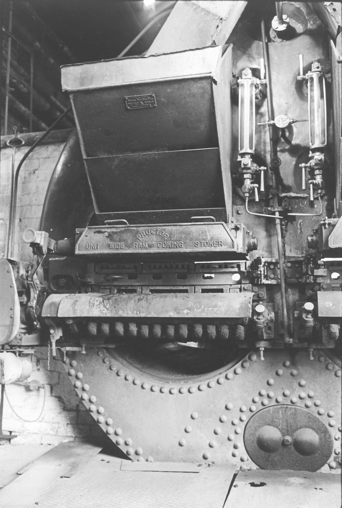
Picture number 85. Negative number 777215.
This is a picture of half, or just over half of the front of the Lancashire boiler. I could go on for some length of time about this, and probably will. What you are looking at there is the front end of a cylinder made of mild steel ¾ “ thick. Riveted construction, nine feet in diameter and approximately 28-30ft long. Two tubes run through the middle of it, this is a Lancashire boiler. A Lancashire boiler is a shell boiler with two tubes, a Cornish is a boiler with one tube. The Cornish boiler was originally invented by Trevithick and the Lancashire boiler is Fairbairn’s improvement on the Cornish boiler. There was a further improvement, I can't tell you who did it, which was a boiler like the Lancashire but with a third tube where the mudhole is below the tubes. This was called the Yorkshire boiler but they were never a success and quietly vanished into history.
There is more to a steam boiler than meets the eye. I don't intend to start airing my knowledge of steam boilers here by going into a lot of esoteric information about the spacing of rivets and thickness of plates. I take the view that there's plenty written down in the text books and if anybody really wants to know all that all they have got to do is to start doing a bit of research.
However, there were certain things about boiler construction which we had to take note of in order to run the boiler successfully, economically and above all, safely. The thing to remember about a boiler of this description or indeed of any other boiler, is that what you are using is a very large pressure vessel, and a very large pressure vessel is a potential bomb. It's a potential danger. In the old days the way they used to describe this was to point out to the innocent firebeater that a Lancashire boiler this size or rather slightly smaller than this, a boiler running at 140psi contained enough energy to lift the boiler together with all its contents 7,000 feet into the air, vertically. Another way of putting it is that you have got to fire this boiler two days and burn 5 tons of coal to get it up to operating pressure and temperature. Another way of putting it is that some idea of the power locked up in a Lancashire boiler could be judged when we were emptying the boiler at the holidays or at any time when we had to do maintenance on it. Anybody who has ever beard the steam coming out of a big boiler like this, out of a 3” pipe sounding like a jet aircraft taking off and blowing like that for approximately 20 minutes will have some idea of the power and force that was locked up in there. This sound was common once at Barlick holidays, everyone knew what it was and it was part of normal life. So a boiler is a very dangerous beast but if looked after is perfectly safe. This was the function of the engineer and the firebeater.
One interesting thing about boilers and boiler insurance and something which a lot of people are surprised about when I point it out is that the government never has anything to do with boiler safety or maintenance. The only thing they are interested in is when something goes wrong with the boiler. This sounds a bit funny but in actual fact the system is quite simple and very sensible. The insurance company who carries the risk of the boiler is responsible for inspecting that boiler and making sure that it’s fit to stand the load that's going to he demanded of it. As simple as that. The only law the government enforces is that a boiler must be inspected and certified safe at least every 14 months. In practice this means once every 12 months. You can go a month over or so and still be legal. [Every ten years the boiler has to have a very thorough inspection and be hydraulically tested to over 50% above normal working pressure.]
So we are looking at the front of a 9ft. Lancashire boiler. Boilers were always classified by their width. The reason for that is that due to the design criteria of a Lancashire boiler, if a boiler's 9ft wide, it stands to reason that for a certain pressure it's going to have a certain thickness of plates and a 9ft boiler is going to be 28 to 30ft long anyway. There is no reason to give any further indication of the type of boiler than to say it’s a 9ft. boiler. Any engineer who has had experience of them knows exactly what you are talking about. This boiler was made by Hewitt and Kellet of Bradford in 1914. It was bought by the mill brand new and I have been told by an old fellow that it was delivered at the mill from Bradford by steam traction engine on a large trailer. He said that the corner of a house had to be taken off in Wapping to allow it through. It would be one of the first things to arrive on the site, the boiler was installed on its settings and then the boiler house was built round it so this boiler would almost certainly be on site during the first world war waiting for the rest of the mill to be built and for the engine to be installed.
All the fittings on the boiler, when I say fittings I mean the fittings which are necessary to the safe running of the boiler not to the firing of the boiler. These are all Hopkinson fittings. Hopkinson’s of Huddersfield, valve manufacturers and one of the most respected names in this field, especially when we are talking about Lancashire boilers. At the time when this boiler was put in Hopkinson’s just about supplied the fittings for every boiler installed in the country. And deservedly so because they had a tremendous reputation for very fine workmanship and very reliable and efficient valves, gauges and associated pipe work.
Looking at the front of this boiler, you'll see that we are looking at one of the tubes. There is another identical tube on the other side. The fire is contained in the front of the tube on a set of cast iron fire bars. You can see the knobs on the end of the carrier bars sticking out under the Proctor coking stoker, under the door where you can see the light shining through the right hand poker hole. This boiler is working hard and inside the furnace the temperatures are high enough to melt steel.
The Proctor unit wide ram coking stoker was a very good stoker there are no two ways about that but like most other things it had its limitations. One of these was that it was only a good and efficient stoker when it was firing at a sufficiently high enough level to give you a complete coverage over the bars. This means that if a Proctor stoker is firing hard it's a good stoker but if you are firing light like we were most of the time, because this boiler playing with the load that it had on it, we were running very inefficiently. Now you can see that by looking at the fire box door you can actually see the fire above the top of the door on the right hand side. Normally you shouldn’t have been able to do that. You should have been able to see a bit of fire through the poking holes in the doors. The doors by the way are very narrow, and immediately below that aluminium plate on the front which has Proctor Unit wide ran coking stoker written on. We very seldom ran at this level and this was one of the reasons why we used to make smoke because we couldn’t cover the bars and we were getting excess air in at the back of the fire. This meant that we were getting incomplete combustion and smoke. A pity really, because the Proctors weren’t a bad stoker. They took quite a lot of maintaining but then every stoker does, there is no such thing as a stoker for burning coal in a boiler that doesn't require quite a lot of maintenance, it has a very hard job to do because inside the furnace there are some extreme conditions, nothing in there can be greased because of the heat, everything is subject to attrition from the heat and also from dust and fine clinker dropping on it which is similar to finely ground glass and it would wear anything.
The construction of the stoker was mainly cast iron. The action of the stokers was that there were two main parts to the Proctor stoker, the fire bars, the knobs of which you can see at the bottom underneath the curved shield and the ram which is inside the box which says 'Ram Coking Stoker' on it. You can see the actuating lever for the ram on the left hand-side. What happened was that as the stoker was working very quietly away, probably only on slow firing, about four or five strokes a minute. On high fire perhaps 30 or 40 strokes a minute. The ram moved forward and pushed a measured amount of coal down on to coking plates at the front which are on top of the door, you can see the back edges of them actually. These coking plates were made of cast iron and soon attained a red hot temperature. They acted as ignition surfaces for the coal when it went in. The heat there began to coke the coal, in other words it began to drive the volatiles off. The idea of this stoker was that as the volatiles moved down the furnace under the action of the draught caused by the chimney they would be ignited and burned completely by the bed of hot coals over which they were travelling. If you had a very small fire, a short fire due to very light load there wasn't enough fire there to burn all the gas off that was coming off at the front and you used to get smoke, it’s as simple as that.
These bars and the grate were self-cleaning. What used to happen was that underneath the curved shield there was a shaft with a lot of cams on it, one cam for each bearer bar. These are the bars with the large knobs on the end you can see under the shield, there were twelve of them. Each bearer bar carried two more fire bars. The cams on the shaft were set so that they moved the bearer bars in a certain sequence. What it meant was that all the bars moved forward together but when they were moving back they moved back in odd ones. This meant that when they were coming back they came back individually and didn't move all the coal back and all the clinker and ash and cinder back. But when they went forward they took it all forward. The net result of this was that the fire was quietly moving away down the firebox all the time as long an those bars were running. The idea was to so arrange thing that they ran at just the right speed to carry the fire to the back of the bars just as it gave over burning and became dead ash and clinker. Then the dead ash and clinker falls over the ends of the bars at the back into the ash pit. Once a day, or whenever is thought necessary, you opened the ash pit door by means of a handle under the bars and slide a long handled curved shovel down and bring the clinker and ash out. Shovel them into a barrow and then lift the barrow out of the boiler house with a small crane just inside the door. We kept the ashes across the other side of the yard and anyone who wanted some for repairing a dirt road could come and take what they wanted. We never had a waste disposal problem.
In other words it was possible to run this stoker all day from starting in the morning to finishing at night without opening the firebox door. This was a great benefit because it meant that you weren't allowing excess air to get into your fires. In the hopper above was the supply of coal for the stoker and above that can be seen the chute which feeds it. This was fed by an auger from the bunker and this bunker faces the boiler. I was actually stood with my back to the bunker when I was taking this picture. In fact I was probably stood in the bunker itself. The hoppers held about 30cwt of coal and under normal circumstances, normal sort of firing, were probably good for about half an hour or something like that. We used to burn on average at Bancroft, with 350 looms running about 1000 tons a year. This consumption varied from about, say, 12 tons a week in summer to perhaps 30 tons a week in winter, but on average we got through about 1000 tons a year. At the time the mill closed down, singles, which was the size of coal to used, and by the way we were working on outcrop coal, we were using open cast because it was slightly cheaper. Singles were about £35 a ton. And so all the total energy charge for the mill was £35,000 a year plus the electricity bill which was about £40 a quarter. This was very cheap for this time for a unit of this size. The Lancashire boiler, even though inefficiently fired, and the steam engine, even though it was an antique, were efficient. What people fail to realise is that the overall thermal efficiency of mains electricity at the point of use in the mill is something like 7%. In other words, out of every 100 tons of coal burned in the power station, 93 tons is wasted. We were more efficient than that and this was why our energy costs were so low.
Fittings on the front of the boiler. On the left of the stoker can be seen at the bottom the electric motor and the two gear boxes and the chain drive in the front in that case which drove the stokers. They drove the cam shaft and an eccentric which powered the ram above. Same arrangement on the other side only right handed instead of left handed.
You can see on the front of the boiler, in between the two hoppers that held the coal a round disc and a pointer to each side. This was the water level pointer and pointed to the gauges at each side which were the water gauges. The pointer is a reminder of the ideal level of water for the boiler. We never used it as a guide but polished it each day. Our guide was the level in the water gauges, these are positioned so that if you can see a level in the glass tubes you are running safely. The water gauge is a glass Pyrex tube which is connected with the space in the boiler at top and bottom through the polished bronze fittings. These are under boiler pressure and they show the level of water in the boiler. The idea was to run somewhere near where that pointer was pointing, more about that later, about water levels in the boilers. These were Hopkinson gauges and were very good. It may sound dangerous, I mean a glass tube on the front of the boiler with the boiler water in it and under full pressure from the boiler, one might be forgiven for thinking 'What happens if that glass tube bursts.' It's a good question, in the early days of boilers it was a disaster because there was that much steam blew out of the broken gauge that you couldn’t hope to get near it. Steam and boiling water, you'd be scalded to death before you got near it. This assumes you weren’t badly scalded when the tube burst because they do occasionally. Two things safeguard against any trouble from that source. The first is that the polished brass case that you can see is a guard, it is open at the back but the front of it is heavy brass and two very thick pieces of very heavy glass. The idea of those was that if the gauge tube did burst they stopped any glass or scalding steam flying forward and hitting the firebeater. It was very dangerous to run with those off in fact. Nobody with any sense ever did it. There was another safety device in the brass cocks at top and bottom of the gauge glass. Inside a chamber cast into the passage which allowed the water and steam to enter the gauge glass was a bronze ball. Normally this sat in the bottom of the chamber but any sudden rush of steam or water past it threw the ball against a seating and closed the passage to the boiler. So if a glass blew the steam and water were shut off instantaneously. Very simple idea and very effective. Very safe and we never had any problem when a glass burst as they did occasionally. The thing that blew them was that erosion inside the tube when blowing the gauges down to test them used to thin the tubes down. I always fitted new glasses every time the boiler was down.
The reason for the cocks at the top and bottom of the gauges, there are two reasons; one in so that you can turn those cocks off for essential maintenance on the gauge, say if the tube breaks; and the other is that during the day you perform an essential operation known as 'Blowing the gauges down’. Blowing the gauges down was done to make sure that the passages from the boiler into the water glasses, the actual tubes, was clear of compo and frothy and sediment. If you didn't blow then down regularly, they quietly bunged up and once they got bunged up the only way you could clear them was to empty the boiler and take the gauges off and rod the holes through the boiler plate out. This is a big job and costs a lot of money because you have got to burn 5 tons of coal just warming the boiler up again. Apart from that, it's tremendously unsafe because at no time do you know exactly how much water you have got in your boiler and that is essential. You have got to know how much water there is in the boiler at all times. So what you do is blow them down a couple of times a day and just make sure that the passages were kept clear. In point of fact, we only needed to blow these down probably once every two or three days because we looked after the quality of our feed water.
Look at the bottom of the gauge and you’ll see there's a small cock, what is known as the Hopkinson tri cock. These aren't piped away anywhere. On a lot of boilers they were piped away to a drain, but in our case at Bancroft there was no handy drain and they were just piped into a bend which we used to leave pointing like that. When we wanted to blow the gauges down we just used to turn that pipe round and point it into the coal bunker and allow the dirty water to blow out on to the coal.
The sequence of operations was, and here I should mention that the valves on the Hopkinson water gauges were very special valves, they were asbestos packed cocks. These were packed with a special mixture of finely divided asbestos and rubber known as ‘Indurated Asbestos’. I think it’s illegal now but I still have some. The idea was that you packed the spaces cast in the body of the cock with this fine mixture while the cock itself was in place and then you hammered it in with specially shaped packing tools made to fit the spaces. When the cock was installed and the steam raised it to boiler temperature this cured the mixture and the packing became an integral part of the construction of the cock. This made a very reliable seal which could last many years under normal working conditions. Notice that they were cocks and not valves. You could immediately tell by the position of the valves whether they were open or closed. This is the reason why cocks were fitted to the gauges. Safety depends on it being immediately clear whether the cocks are open or shut. You can walk into any boiler house in the country and see from one look whether the gauges are operating or not.
The sequence of blowing gauges down varied, different people did different things. The way we used to blow them down, the way I always used to blow them down was to first of all swing the drain pipe out till it was pointing out into the bunker. Then close the top cock, and open the small cock at the bottom. This meant there was a passage from the bottom aperture in the boiler plate to atmosphere so a strong jet of superheated water blew through taking any sediment with it. Close the bottom gauge cock and open the top one, this allowed steam to rush down the tube to atmosphere and cleared the top aperture and the glass tube. This was when the tube got eroded. Then close the top cock. Close the tri cock. Open the bottom gauge glass cock very slowly and fill the glass with water. Then open the top gauge cock and allow steam in. The gauge glass will slowly equalise pressure and will give a true reading after about 30 seconds. You now know that those gauges are telling the truth and can rest easy in your chair.
You can get a lot of information from the gauge glasses apart from the water level. If you see the water level fluctuating in the glass you know that a lot of steam is flashing off. Rather like a rolling boil in a kettle. If you see water running down the glass from the top of the gauge it’s an indication that the boiler might be priming. That is the water has frothed up and is above the level of the top hole in the boiler plate. In other words your water is dirty and you might be getting very near to priming, which in where froth and water and muck goes up the steam pipe into the engine, a dangerous condition.
A very common question that is asked by a boiler surveyor if he doesn’t know the firebeater or the engineer is “What do you do if you can’t see any water in the gauge glasses. The inexperienced bloke will say “Christ we rush down in the cellar and get the feed pumps going straight away." That isn't the right answer, what you do is blow the gauges down because what you’ll probably find is that it wasn’t a question of having no water in the glass, you have got too much. The level has risen beyond the top of the glass and therefore the glass looks as though it's empty. If it's clean water it'll look as though there is no level so the thing to do is to blow it down first, and see what the level settles down to. If the level vanishes out of the bottom of the glass you are low, if it vanishes out at the top you have got water. Gauge glasses are always fixed on the boiler so that if water shows in the bottom of the glass you have 2” over the highest part of the furnace crown which is safe but marginal. Low water is when the furnace crowns become exposed, they are not cooled by water and become red hot, lose strength and collapse or rupture. That’s when you get boiler explosions. It’s a very dangerous condition. The way to avoid it is always to keep your water at least at working level.
Now, a word about working levels. One of the beauties of the Lancashire boiler is the fact that it holds a lot of water. Some boilers water capacity is limited and they are very free steaming boilers but they have very little reserve. Now a lot of people think that the reserve is something to do with the volume of steam contained above the water level, in the space in the boiler which isn't taken up by water. This is a fallacy. The steam in the space above the water in a Lancashire boiler might run the engine for 30 seconds, if that. Your true steam reserve is in the amount of water that you can afford to lose without endangering the integrity of the boiler.
This needs some explanation. The first thing to realise is that if you lower the pressure on a body of superheated water it has to get rid of heat immediately until it has got down to the correct temperature for the lower pressure. It reacts like champagne when the cork is popped, the excess gas rushes off in strings of bubbles generated in the liquid. Superheated water does the same thing but not because of dissolved gas, it’s because the only way it can lose heat is to generate steam. The next thing to realise is that the white stuff that comes off boiling water isn’t steam. It’s condensed water in very fine droplets. True steam is water raised to a temperature where it becomes a gas.
The speed at which you can take steam off a boiler depends on the rate at which you can burn coal and put heat into that boiler and the reserve of water you have which can flash off into steam as the pressure drops. A brief description of what flashing off means would be useful. If you could get a bucketful of water out of the boiler and keep it under pressure and put it on the boilerhouse floor and then reduce the pressure to atmospheric it would explode like a stick of dynamite as the water expanded to probably 10,000 times its volume instantaneously. This is what happens when a boiler ruptures and is the reason why they are so dangerous.
Suppose you have a bigger demand on the boiler than the coal burning in the furnaces can supply. Boiler pressure starts to fall and when it does it is a controlled version of what happened to our bucket of steam. The water in the boiler starts to flash off and make up the shortfall. The length of time this can be allowed to go on depends on how much water you can afford to lose before the water level over the furnace crowns becomes critical.
Herein lies the Lancashire Boiler’s steaming capacity. If you know you are going to have a heavy demand you get your pressure up but at the same time open the feed pumps up and raise the water level to say an inch from the top of the glass. This means that even though the pressure may fall a little you can carry on generating perhaps 50% more steam than you are putting heat in. Actually there is no such limit because the boiler would make steam as long as there was superheated water in the boiler whether the fire was lit or not. I once ran the weaving shed for over two hours with no fires in. This wasn’t from choice but circumstance and even I was amazed how long it ran for..
So, here we have a clue to the best way to manage a Lancashire boiler. You may remember me saying that I improved the feed pumps at Bancroft and I said I’d come back to the subject. The secret of running a Lancashire boiler most economically depends on having reliable and easily controlled feed water pumps. When I had finished my improvements we had these.
We used to start in the morning with the water an inch down from the top of the gauge glass, about 140psi of steam and a fairly full fire running at say 75% of capacity. If the boiler pressure started to drop, say the tapes were boiling size and using a lot of steam, the trick was to leave the fires alone but cut back on the feedwater and allow the level to drop back. When the pull on the boiler diminished, the feed was opened up again to a level which kept the pressure steady but allowed the water to build again. So we weren’t adjusting for demand with the fires but with the feedwater. This meant that the fires were burning steadily and at their most efficient. If we found out we were getting into trouble with high or low water we adjusted the fires. For low water we speeded the fires and the pumps. For high water we slowed both.
Another factor comes in here which needs addressing. Every 11 degrees Fahrenheit you raised the temperature of the feedwater, you gained 1% on the efficiency of your boiler. This is the reason why mill owners spent a lot of money on economisers which were a nest of tubes in the hot flue gases through which feedwater was pumped to the boiler. This extracted heat from the flue gas and transferred it back to the boiler. When new or in good condition the economiser worked under the same pressure as the boiler thus increasing its efficiency even further because you could superheat the water. Our connies at Bancroft failed the test long before I arrived on the scene bit we could still run them at atmospheric pressure. What I used to do was have one pump, the Pearn, pushing water round the economisers and returning it to a hot box in the cellar with a float switch on. When the level reached a certain point the Brown and Pickles pump would kick in and pump the almost boiling water into the boiler. The overall feed was governed by a simple by-pass pipe between the delivery and the intake on the Pearn. If you shut it the pump delivered maximum flow to the connies. As you cracked that valve open the flow diminished. The Pearn ran constantly and the flow of water to the boiler was controlled by that one small valve. It was a brilliant system and we had perfect control over the feedwater and thence, the output of the boiler.
SCG/23 September 2003
6,475 words.
LANCASHIRE TEXTILE PROJECT
TAPE 78/AI/11 (Side two)
THIS TAPE HAS BEEN RECORDED ON MAY 2nd 1979 AT 13 AVON DRIVE BARNOLDSWICK. THE INFORMANT IS STANLEY GRAHAM WHO WAS THE ENGINEER AT BANCROFT MILL AND WHO HAS BEEN THE INTERVIEWER ON MOST OF THE TAPES..
[This is the last transcript and I’m afraid I got carried away on 78/AI/11 part one and overlapped with some of the subjects dealt with here. No matter, I’ll probably give some additional information]
When I first went to work at Bancroft they were in a terrible state because the old Pearn pump which they had in the cellar wasn't capable of pumping hot water to the boiler fast enough to make up for the water which was being evaporated in steam to keep the engine going and supply the process steam. In effect what this meant was that you started up in the morning with your water right up at the top of the glass and the pump just couldn't keep up, you were losing water all day. If you hadn't done something about it you would have got to the stage before the end of the day where the water level was so low in the boiler that the compound valve would have blown and the boiler would have lost its pressure. More about the compound valve in a minute or two. The only thing we could do was increase the rate that water was being pumped into the boiler by some means or another. There were two ways of doing this, we could either use the Weir steam pump which sent the water round the connies and into the hot box to pump water straight from the ‘hot well’ into the boiler to supplement the delivery from the Pearn. Or we could revise our pumping arrangements.
When I first went in to the engine house I had a lot of things to sort out and while the pumps were a priority I had to find a temporary solution. The first thing to recognise is that whatever I did I was going to be pumping large quantities of cold water into the boiler which was inefficient. Another thing to bear in mind was that it is a characteristic of all displacement pumps that the hotter the water, the less efficient they are at shifting it. George Bleasdale had taken the easy way out and simply used both pumps to put cold water in all day. He kept his water levels up but wasted a lot of coal.
We held the matter at bay by starting with a full glass and high pressure in the morning and ignoring the water level falling back. At dinner time, which was an hour in those days, we pumped water as hard as we could at the boiler and fired hard. If the pressure started to get away on us we put both pumps on the well and shoved cold water in. We could get the water up to a reasonable level for the afternoon but by stopping time we were in the bottom nut on the gauges. I used to leave the Pearn running, go home and have my tea and come back afterwards to stop the pump.
There is another problem about putting cold water in the boiler. When the cold water meets the hot water in the boiler the temperature boundary causes electrolytic corrosion in the metal of the boiler. To a certain extent this is mitigated by having a piece of pipe on the back of the feed valve in the boiler which was about eight feet long and perforated with ½” holes. This allowed the water to get up to temperature and most of the corrosion attacked the pipe which was sacrificed for the greater good of the boiler plates.
I had a word with the management, persuaded them that something had to be done and had a word with Newton Pickles. It just so happened they had a large three throw pump in stock which they had bought back out of Finsley Gate mill when it closed and had reconditioned it for Hill’s Pharmaceuticals in Harle Syke but they had never got on with fitting it. This was a Brown and Pickles pump and was different than most three throw displacement pumps in that the valve box on the front was detachable so that it could be taken down to the shop and put on the borer to reface the seats. This clack box is the heart of a displacement pump. The biggest problem with the Pearn was that it needed the clacks completely refurbishing but as the mill couldn’t run without it we couldn’t take it out of service to do it.
So I bought the B&P pump complete with a ten horse power Horace Green motor and bed for £220. B&P would erect the pump for us on our bed. The starter and wiring cost another £65. These prices sound ridiculous in 2003 and will be even more unbelievable in a hundred years. Now what this meant was that me and Bob Parkinson, the firebeater as it was in those days had to pour the concrete bed ourselves with foundation bolts in the correct positions. I forget how many yards of concrete were needed but I know Bob and I were glad when we had carried it all in in buckets and finished it. B&P came down and dropped the pump onto its bed. If you look in the engine house you’ll find the hole I cut in the floor to drop a chain through from the gantry above so we could get a lift. I had to fabricate all the pipework from old pipe in the mill. The pump was originally made to feed four boilers and run at 100rpm. I fitted a larger pulley and cut it back to 45rpm and it was wonderful, we could put water in the boiler whenever we wanted.
I didn’t stop there. As soon as I had a good pump I took the Pearn off line and rigged up a fitting to bore the seats in situ. I ground the valves in and it pumped like a hero! There is nothing more satisfying for me that getting a result like that with hardly any outlay.
A word here about setting clacks on pumps like this. The mistake that almost everyone makes, including the manufacturers, is to give the clack too much space to lift. You’ll see a lot set to about three thirty seconds of an inch or even more. I used to give them a shade under a sixteenth, this is plenty. A space this size on the periphery of a three inch clack can pass a surprising amount of water. Think of a saw cut round a three inch pipe, you’d never keep up with it. The big pump was set to a sixteenth.
Once we had the Pearn sorted Bob Parkinson suggested we fit a by-pass between the outlet pipe and the inlet so that we could bleed water round to adjust the flow up on to the connies. This was a brilliant idea and we found we could make incredibly fine and reliable adjustments to the flow. Bob soon got used to it and we ran with the Pearn permanently on line and the B&P was controlled by the level of the water in the hot box by a mercury float switch. It used to start up and empty the box in a few gulps, most impressive.
We were now running the fires on constant load and adjusting pressure with water and the result was that coal consumption dropped by two and a half tons a week on average. The pump paid for itself in three weeks. The management were impressed but more importantly Bob and I had a far easier job, no more coming back at night, no sweat during the day, wonderful set up which I would recommend to anyone. We made other changes in the boiler house, re-routed pipes and altered settings and eventually saved another half ton of coal a week. We never got any thanks or a bonus. I sometimes wondered whether they even noticed.
A true story for you. Peter Birtles, the managing director, came into the yard one day and congratulated me on the fact that there was only a wisp of smoke coming out of the chimney. We had no instrumentation on the boiler to tell us what combustion conditions were. My method was to get the fire settled down and then adjust the dampers which controlled the amount of air going through the fires until we were making a bit of smoke. I would then open them a crack and all you could see at the head of the stack was a faint haze of blue smoke. This was as near perfect as you could get it. Enough air for combustion but no excess to cool the flues down. I turned to him and told him that the trouble was that he couldn’t see what I could see. I could see pound notes fluttering out of the top of the stack and drifting down over Barlick. I said that if he could see them he’d do something about it immediately. He said I was being silly so I told him that I could come up with a scheme that wouldn’t cost anything and would save him at least 15% on his fuel bill and get the ‘nuisance man’ off our backs. He perked up and asked me to do it.
What the management had missed was the fact we had 200 tons of stock coal up the yard which was worth £7,000. In addition the government were giving a grant for any scheme which could show a saving of 10%. New underfired stokers which could support any load with complete control over air supply would eliminate the smoke and cut our fuel costs. The plan was that we did the conversion that would cost £10,000. £3,000 would come from the grant and the other £7,000 from burning the coal stock. At the end of the payback period if we started ordering coal again at the same rate we did with the old stokers in eighteen months we would have paid for the stokers and replaced the stock. Everything after that was a saving.
They went away and thought about this and about two months later the management came back and said “Start burning the stock.” I asked about getting the orders in for the new stokers and was told I would be informed later. I went in the boiler house and told John Plummer he was looking at the biggest pillock in Barlick. He asked why. I said “I’ve just closed this mill!” I was right. They took the £7,000. Never allowed me to buy any more stock and the first letter they had after that about smoke emissions they used as an excuse to close the mill. The bottom line was that we were now owned by Pakistan money and they were buying mills, stripping the assets and closing them down. I have an idea they were destroying capacity so it couldn’t be a threat to them in the future. Doug Hoyle, who was MP at the time told me he knew of about a score of mills that had gone the same way.
That’s enough stories. What I hope I’ve conveyed is that there was more to running a boiler than meets the eye. Bancroft was an old plant but we didn't do so badly. Within our limits we ran an efficient power plant. Most of this was due to attention to detail. The magic wand was a good example. Newton once told me that an air leak in the brickwork settings the size of a cigarette wasted a barrowful of coal a year. I’m certain he had no proof of this but the principle was sound. The more air leaks you stopped the more efficient your boiler was. The magic wand was a piece of half inch conduit with a piece of rope in it. We kept is submerged in a paraffin bucket so it was soaked right through. When you lit the end you had a nice smoky flare and the procedure was you went round your settings with the wand and anywhere the flame was sucked into a crack or under a flag you bunged the place up with fireclay. It sounds crude but it was a wonderful thing to do. All the leaks added up.
I’ve mentioned the pressure that we ran the boiler at, the pressure gauge, actually you can't see it on this picture. If you look above the water gauges you’ll see that there is a pipe coming out of the boiler above them. This had a large brass pressure gauge on it with a dial about 1ft across which was marked from 0 to 320psi. A pressure gauge for a boiler is always marked up to twice the rated pressure of the boiler so that the gauge is always working well within its capacity and is going to be long lived and accurate. The maximum pressure on this boiler, the insured pressure was exactly what it had been installed at, 160psi and had never been varied. This boiler was in absolutely perfect condition. It really was amazing the condition of that boiler. The attrition on the tubes was so small as to be negligible; and this was after having been fired for almost sixty years. The construction of those boilers was very good, this would probably be made of Low Moor Iron, very good quality iron and mild steel came out of that Low Moor Iron works and this boiler would be made of it.
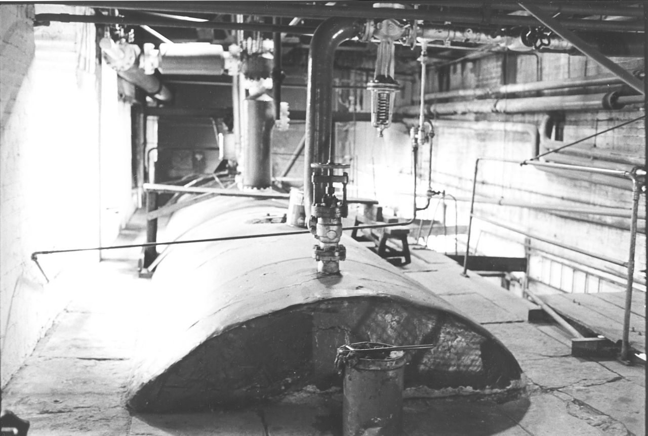
Bancroft folio, miscellaneous picture number 86. Negative number 777220.
What you are looking at here is the top of the boiler poking through the boiler settings. At either side, the flagged area at either side of the boiler top is the roof of the side flue. Here again I am not going to try and go into a detailed explanation of fluing arrangements on a Lancashire boiler. Anybody who is interested can find them out for themselves, there are plenty of detailed descriptions available. Sufficient to say that every part of the boiler which couldn't be seen either from the top here or from the boiler house floor was inside the settings and bathed in hot flue gas while the boiler was running. The portion of the boiler which stuck out of the settings, that's this portion here that we are looking at, was covered with a four inch thick layer of pig muck, that’s asbestos insulation to conserve heat, to try and stop as much heat as possible escaping. That’s right, asbestos. At the time this picture was taken it was still legal to use it even though it was known to be high risk. The bottom line was that the asbestos industry lobby was still managing to hold back action against them by lobbying and misinformation.
[See magic Mineral to Killer Dust by Geoffrey Tweedale. Pub. Oxford, 2000. ISBN 0-19-829690-8 for a very full account of the activities of Turner and Newall in this field.]
We swept the top of this boiler frequently and the dust was choking. I am still wondering 25 years later whether I’ll ever regret doing this.
You’ll see that there are numerous pipes coming out of the top of the boiler. They are in order from the back: The connection for the tapes, a 3” pipe going up to the tapes. You'll see that there is a queer sort of a thing there with a spring in the bottom of it in that pipe just beyond the bend, that's a reduction valve which reduced the pressure of the steam to the tapes down to 80psi. This ensured that the tape department was supplied all day at a constant pressure of 80psi. Notice that there is a drain on the bottom of the 3” pipe which dewaters this steam main. There is a by-pass on it for blowing it down every morning. A steam trap is fitted which allowed water past but not steam. This is fine for dealing with small quantities during the day but when you first put steam into a cold main you have to have a faster way of getting the water out, hence the by-pass.
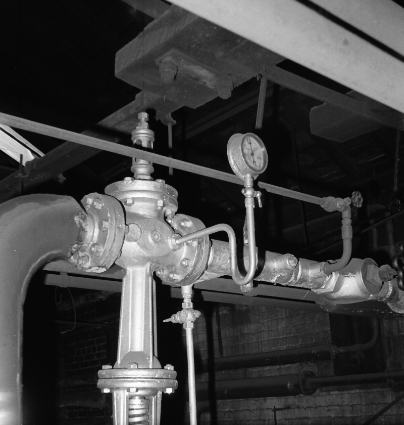
The next pipe moving along the boiler plainly to be seen but slightly out of focus is a very large pipe coming out of the boiler top and going over to the left into another large pipe. This was the main steam range out of the boiler, all the steam for the engine came out of there. On top of it, you can't see it very well in this photograph is a very large valve, what we call the crown valve or junction valve. That valve, when shut down, shut the boiler down completely and stopped all steam getting out of it. [Assuming the tape valve was shut.] That was a 6” main and went straight on to the engine. There is a branch comes this way off that main, you can see the flange and the pipe that comes out of it into a manifold. That manifold fed all the heating mains into the mill. All the pipework that you can see slung about in the boiler house apart from that was connected to either the economisers or the heating system.
The heating system at Bancroft was terribly inefficient and very wasteful. And if you have studied your pictures in the weaving shed at all carefully you'll see that all it consisted of was 2" pipe slung up about 8ft above the floor in the weaving shed and going round in large ranges. There were three ranges in the weaving shed, each of them about 3,000 ft long and they were fed with steam at boiler pressure. That is up to 160psi and they were remarkably inefficient. I’ve seen me in there trying to warm that shed up at 2 o'clock in the morning, putting steam in at 140psi and watching the temperature in the shed fall. That’s no exaggeration. I’ll speak more about this in a while.
You may wonder why such a system was ever installed. There is method in the madness. There are far more efficient ways of getting heat into a large space like that but they all tend to dry the warps out and cause problems with weaving. This method was all wrong but it didn’t damage the warps as the heat crept down slowly from the roof.
Beyond the steam main are two more fixtures on the boiler which were common to every Lancashire boiler of this size. The first one was the compound valve and the second one was the dead weight safety valve. The dead weight valve had the function of allowing any excess steam pressure to escape. It was set at 160psi and if the pressure rose above that it would lift and get rid of steam as fast as the fire could make it. Normally, the only time this valve lifted was when the boiler surveyor asked us to demonstrate that it operated at the correct pressure. This happened ever year when we were working after the annual inspection. The inspector would turn up and we gradually brought the pressure up until it blew. I never liked this because it upset our routine and made the engine uncomfortable. If, for any reason at all, that valve failed or couldn't cope with the amount of steam that was being made, the compound valve which is a combined high pressure safety valve, and low water valve, would come into operation. That used to open at 165psi and it would let off steam as well. In other words, there was never any danger of the safety valves not being able to get rid of as much steam as the fires were making if everything in the mill stopped suddenly while we were firing flat out. Bear in mind that this was possible, say if we had a fire or an accident.
The compound valve was also a low water warning valve, this was why it was called ‘compound’, it served two functions. There were two types of low water warning one blew a whistle the other type, and this was what Bancroft had, opened the safety valve. What it consisted of was a float which floated in the water in the boiler. It was adjusted so that as long as the water level was above 2” on your gauge glass it didn’t operate. In other words, 4” above the top of the tube. Now, a very peculiar thing about the Bancroft compound valve was that for years it wouldn’t work. I did everything I could to make it work. We stripped it down, re-built it, did all sorts and we couldn’t get it to work. One day, all of a sudden, it cured itself. My theory is that we had missed weighting one of the valves correctly, these valves were noted for being difficult to balance. The only way Newton did it was to set it so that it was balanced when his small hand hammer was on the main balance weight. I think that what had happened was that scale had gathered on the float and it had found its own balance. Whatever the reason, it suddenly started working on its own. The only trouble was that it used to blow 4” above the bottom of the gauge glass which was rather high. Now this was no hardship because we never used to get the water level down that low after we improved the pumps. The fact was that the Bancroft compound valve did work but it didn't quite work at the level that Hopkinson’s had designed it to work at. In other words if you were firing that boiler and you let the water get down to within 3” of the bottom of the gauge you could expect that valve to lift any minute. If it did lift, of course it dropped your temperature, the pressure in the boiler drastically and you were into trouble straight away keeping your engine going and keeping everything working. So of course you avoided that situation. The fact is that it would have given you plenty of warning if you had been running into low water conditions for some reason beyond your control, like a break down of a pump or your firebeater falling asleep or a complete idiot running the boiler, something like that. You would have got very adequate warning.
The top of the boiler was a very dirty place, it's not so bad on this picture, we’d evidently had a whitewash round. We used to whitewash and brush round, wipe the painted top of the boiler down with a piece of oily waste. We used to do everything we could to improve things but the boilerhouse was a dirty place, there is no getting away from it. Running a Lancashire boiler under the systems we operated under was a mucky job.
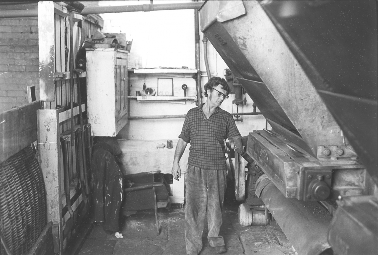
Picture number 87. Negative number 7710212.
This is a picture of John adjusting one of the clocks on the stokers at the front of the boiler during the day when it's running. The ‘clock’ was a graduated dial on the infinitely variable reduction gear that controlled the drive to the stoker from the electric motor mounted at the bottom of the unit.
You can see that we had an extremely efficient arrangement for keeping coal in the bunker, we used to have old skip lids between two planks. This was actually a very practical method of containing the coal. When the wagon delivered the coal was just above the level of the top board. This was a good time for the firebeater because though restricted in the space he had in front of the boiler, he didn’t have to shovel coal to fill his hoppers. He just switched the auger on and the hoppers filled automatically. As soon as the coal level dropped in the bunker the skip lids could be pulled out and stacked in the old boiler house next door giving plenty of room in front of the boiler and letting more light in. It was very easy to trap your fingers between the rake handle and the skips when they were up. There was a gap under the bottom board which could be used for getting at the coal with the shovel when you were banking the fires at night.
This picture gives a very good idea of what went on during the day in the boilerhouse. That was John's job, to keep his eye on the steam pressure and make any necessary adjustments to the water feed or the stokers. Keep the hoppers filled and most importantly, take the occasional walk round the mill to see what was going on. This was a pleasant part of the job and actually essential to running the boiler.
Firing a single Lancashire boiler for the mill was like a game of chess if it was done properly. Because of the large amount of water in the boiler, about 5,000 gallons, we had a great capacity for withstanding overload. A boiler this size on high firing will make about 8,000 lbs weight of steam an hour. That means it will convert about 800 gallons of water into steam. For short periods, by shutting the feedwater off, you could stand double this load. This was very handy but if you think about it it meant that the boiler was very slow to react to increased rates of firing. If you were going to keep your water feed and steam pressure dead level you had to anticipate the demands of the mill. It took 20 minutes for the boiler to react to a change in firing load. So John’s walks round the mill were vital. Twenty minutes before I increased the load on the engine by putting the shed light on, or the tapers started a new set or boiling up a next batch of size, John opened his fires up an appropriate amount. The result was that when the load hit us he was ready for it. The needle on the pressure gauge never shifted. This was the mark of a good firebeater.
There is a consequence to this which isn’t immediately obvious. Every time the pressure alters on a boiler the metal has to adjust to it. In effect it swells slightly on high pressure and shrinks on lower pressure. The metal actually expands and contracts. This is a very small movement but over the years it tends to damage the boiler and result in fatigue cracks, loose rivets and leaks. The worst duty for a boiler is in a brewery where tremendous demands are made for steam to heat vats and tanks. The best duty is running an engine with a good firebeater because the pressure is rock steady all day.
One small point here as well. The firm didn’t supply overalls. We had to buy our own. Jumble sales were a good source of old trousers and shirts!
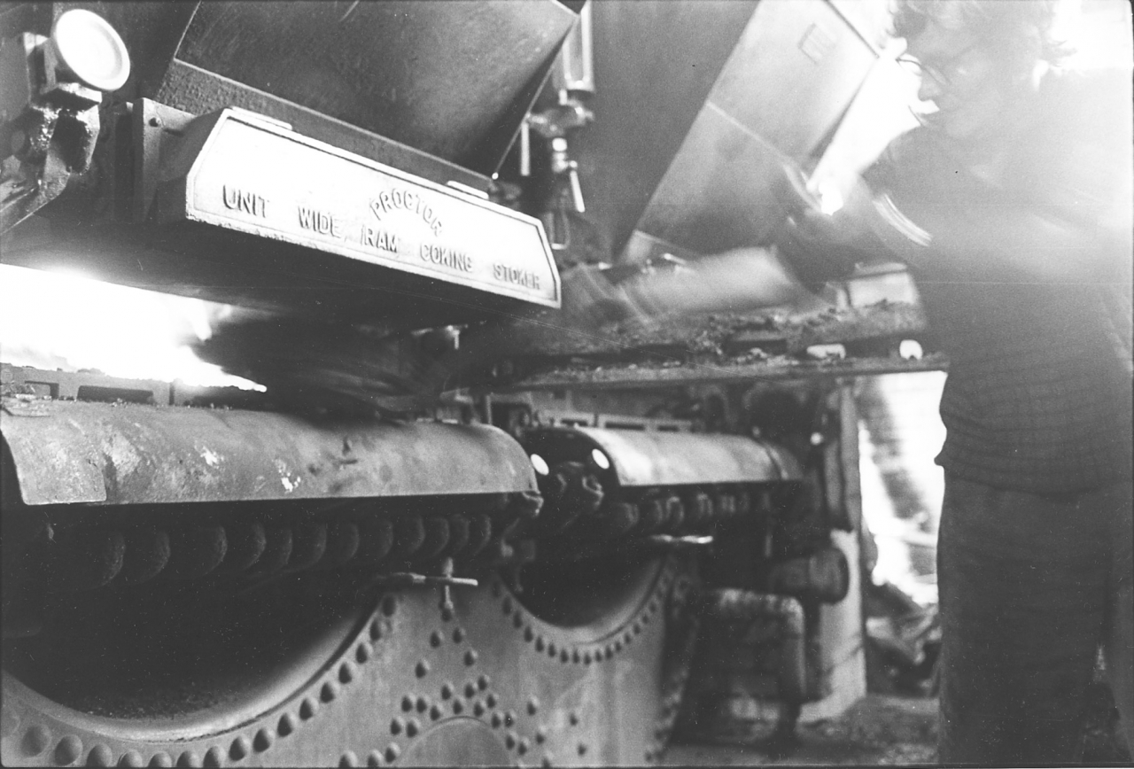
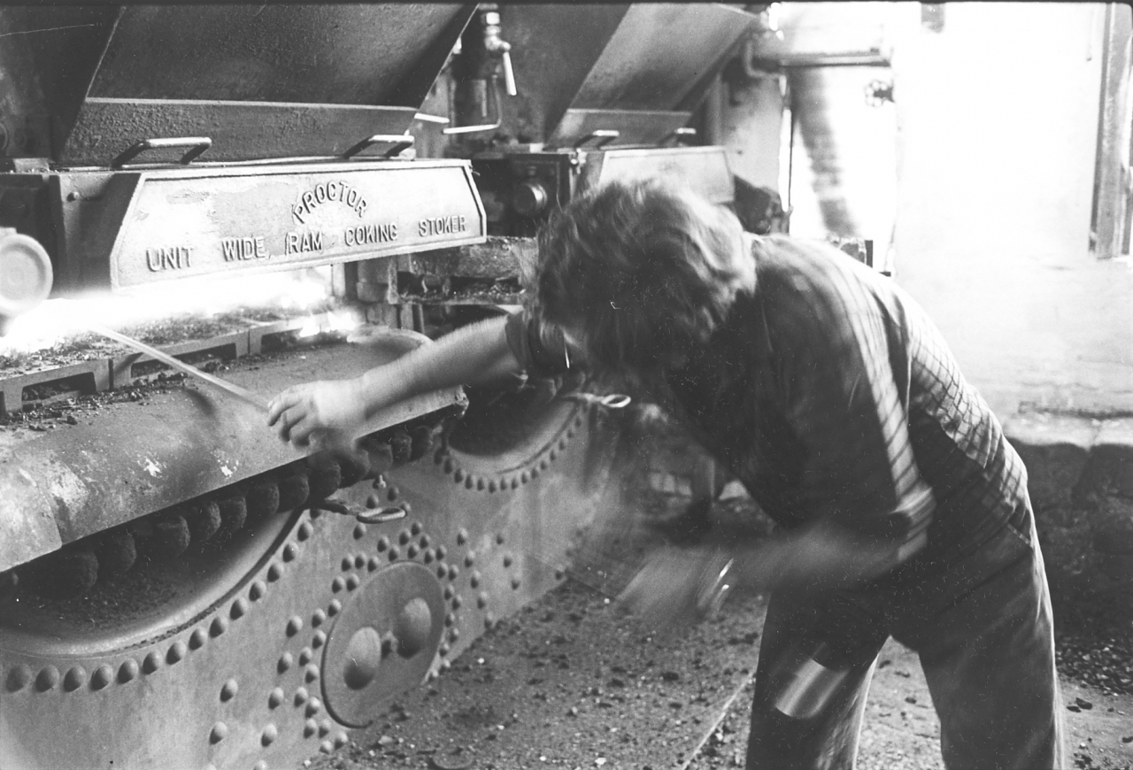
Pictures number 88/89. Negative numbers 7710229/19.
This is a bit of old fashioned work. We called it handballing. What John's doing there is firing the boiler by hand. This was not normal practice. On this particular day the gearbox on the right hand furnace had failed and in order to keep the mill going we had to fire by hand. Normally, on a hand fired boiler the firebox door is half the size of the three foot diameter furnace. Ours was only 4” high so shovelling coal in was an art. Remember that you had to get the coal six feet in to the back and precisely placed. The trick was to take small shovelfuls and it took a bit of doing, it took a lot more doing than you'd think.
Keeping a firebox supplied with coal is a lot more complicated than it looks. The usual Hollywood image is of large men doing a lot of grunting and shouting while they throw large lumps of coal on to a fire. Forget it! The aim is to cover the whole of the firebars with a layer of coal that the draught can penetrate easily, you have to have air to get combustion. If the layer is to thin, too much air will get through and cool the flue gases down. Too thick and it will block the air and not burn properly. The worst crime is to have holes in the fire which cancel out an equal area of fire because they are not burning anything but letting large volumes of cold air in.
When you are firing a grate of any description, always remember to fire it round the side and then down the middle. In other words, a firebox that size which was six feet long and three feet wide you put about seven shovelful down each side, and four or five down the middle and that will give you a flat bed. If you throw coal into the middle it won't scatter to the outside, you’ll finish up with a big heap in the middle. If this was a normal firebox opening John would get it right and not have to rake it afterwards to make it flat, it would be laid flat by itself. We were hampered with the narrow opening and on picture 89 you can see the consequence. John has fired his furnace and is making sure he has got it right by raking it flat. Remember that it’s hot enough to melt steel in there. The heat is burning the hairs off his right forearm and scorching his face. The intense glare isn’t doing anything for his eyes either. If you could see his face he will have his eyes screwed up to protect them.
When I was firing like this I used to put three down either side right at the back and then put a couple in the middle, and then put three more down either side nearer to me and another couple on the middle and then I’d attend to the front corners. You could burn a bed four or five inches thick and once you had the door closed it was a good fire. It took a few minutes to drive the volatiles off and during this period you got a bit of smoke. This was the trouble with hand firing and was one of the reasons why Fairbairn developed the Lancashire boiler. The theory was that if you had one firebox running white and clean while you were stoking the other, any volatiles that were driven off met the hot flue gas from the other fire in the downtake at the back of the boiler and burned in the flame bed or sole flue under the boiler. This could work but it was hit and miss. The biggest flaw was that in order to fire you had to open the door. This automatically meant excess air and bad combustion.
There is a dividing wall in the downtake called the mid feather which keeps the two streams of gas separate until they meet in the flame bed. This was fitted because it was quite common for the volatiles to explode when they hit the hot gas from the other flue. This could develop into a series of small explosions and set up a vibration which was very bad for the brickwork. The mid feather ensured that these ignitions took place in the flame bed which was a far more solidly protected space with the boiler above and the foundation walls at each side. Some engineers called the downtake the ‘explosion box’ for this reason. At Ellenroad there were explosion lids at the top of each side of the downtake. The theory was that the heavy lid would jump and relieve the pressure.
Here’s something that you won’t believe and is not in any text book. The downtake of the boiler is the hottest part of the flues. My old flue chap Charlie Sutton once told me that in the old days they always used to look for melted gold in the dust in there. He reckoned that more than one nagging wife had finished up down there. He also said that occasionally on hospital boilers they had found amputated limbs in there. Not a bad place for getting rid of waste like that. Occasionally someone would bring us confidential papers or a dead animal to burn. We used to do this when burning off at stopping time. The paper wasn’t so bad but the dead dogs were never burned within a fortnight of flueing. Charlie said it took ten days for the smell of burning flesh to dissipate. Too many stories! One last little known fact about flues. The flame bed of a Lancashire boiler that had been fired well over a long period was as white as snow. Don’t ask me why, it was covered with a thin layer of white flue dust.
This is a good place to describe how a Lancashire boiler is managed during the periods when the engine is stopped overnight or at weekend. The mass of water, steel and brickwork that makes up a Lancashire boiler and its settings takes a lot of heating up from cold. It was a fact that after the weekend stoppage the boiler didn’t achieve peak production until Wednesday when the heat had reached its peak in the settings. It would have been easier in terms of boiler management if we could have fired 24 hours a day and seven days a week. However, we had to accept normal working hours and manage the boiler accordingly. The way we did this was to make sure the boiler kept up to 140psi 24 hours a day. This needed heat input during the night and the way we did this was to ‘bank the fires’.
Half an hour before stopping time you could always see the firebeater vanishing down the road on his way home. This was because he had finished for the day. He had made sure that over the last 90 minutes of running he had gained on his water and had got it up to about an inch below the top of the gauge glass. Then what he did was clean his ashes out an hour before stopping time. About 45 minutes before stopping time he made sure his hoppers were empty and opened his firebox doors and raked his fire out level over the bed and allowed it to burn off. This was a very fierce fire covering the whole of the grate area and steam pressure would rise a few pounds.
When the fire had burned off he was left with a grate covered with clinker, fused ash, and an occasional patch of red coals. He pushed all the dead clinker over into the ash pit and moved all the red fire down to the back of the bars. Then he shovelled about thirty shovelfuls of coal into the box in a heap against the dull coals at the back.
He repeated this one the other furnace and then shut his dampers down until they were just giving enough draught to move the smoke away up the flue. Then he went in the cellar, shut his pumps down, locked the cellar door and went back to the boiler and shut the feed valve into the boiler.
He now has a boiler full of water and with two slow fires in. Shut the boilerhouse door and off home John, job well done.
Meanwhile the engine is still running and the steam pressure might drop 20psi in the last hour but this was no problem. Overnight the boiler will lose about two inches on the gauge glass because of the warmer steam going into the engine but the banked fires will slowly burn and when you come in first thing in the morning you’ll have about 130psi on the pressure gauge and a half full gauge glass. All you have to do to get the boiler going is fill the hoppers, rake the banked fire to the front of the bars. Chuck a couple of shovelfuls on, shut the door, open the dampers and when you see white fire on the poker holes in the door, set your stokers on. Then open the feed valve, go to the cellar, open up down there and set the feed pumps on for a very slow feed. Go and brew up, in half an hour you will be ready to start the day. This is stuff you won’t find in the text books and is the value of prime source material which is what the LTP is all about.
I have told you about the problems we had with the Proctor stokers running on short fires. I decided to try an experiment to see whether I could improve things. The basic problem was that due to the fact that the stokers weren't working at high enough capacity I was getting excess air at the back of the fires and inefficient combustion. The answer seemed obvious, I heeded longer fires. So what I did, I blocked one of the tubes off. I blocked it off simply by fitting a cover over the ash pit and blocking all other air holes up with slag wool. The idea was to fire on one tube with a heavy fire and thus gain efficiency. The question was, would one tube run the mill? There was only one way to find out. We got everything ready the night before and went home. Now the firebeater I had at this time was useless, he had replaced a good lad and didn’t last long. He never turned in the following morning so I was on my own.
I started the day with a full gauge glass and almost 160psi with a full fire in the one tube that was running. By dinner time I had got down to 75psi and hardly any water and the engine was struggling with the load. The problem was that as the pressure dropped the engine used more steam and it was a vicious circle. I had to ask the tapes to stop and during the dinner hour I fought to get steam and water back. I should say that I was in no trouble because Jim knew I was trying a new strategy. He also knew I was on my own and came down to see if he could help in any way. By starting time after dinner I had gained a little pressure and some water and because the tapes had shut down I managed to stagger on until stopping time. Needless to say, the last job that day was to rip out the modifications, light a fire on that side and fire the boiler up to 150psi with a full glass and banked fires. The firebeater came in the next morning, he had been suffering from a headache! It was the hardest day I ever had at Bancroft and perhaps the lad was brighter than he looked. The experience wasn’t wasted though, I had proved that it was mission impossible. It had been a day of heavy demands because the tapes had heavy warps in. The tapes were the people that used our steam and used the coal. Nobody ever knew how much coal it took to tape a complete set of back beams in say 8’s twist. That’s very thick twist and the heavier the twist, the more size it takes and the harder it is to dry on the cylinders. They could eat steam and the thing that made it worse was that when we sent steam up there we never got it back again. No, that isn’t a mistake, whenever steam was used in the mill we tried to get the hot condensate back to the engine. This was the best feedwater there was, perfectly clean and at high temperature. If you could have fed a boiler on nothing but condensate you wouldn’t need any boiler treatment. We used to move heaven and earthy to return every drop of condensate we could get, and I should think at Bancroft we were fairly efficient in this respect for an old plant. My comment about the tapes is because they were the biggest steam users and none of the steam came back as condensate.
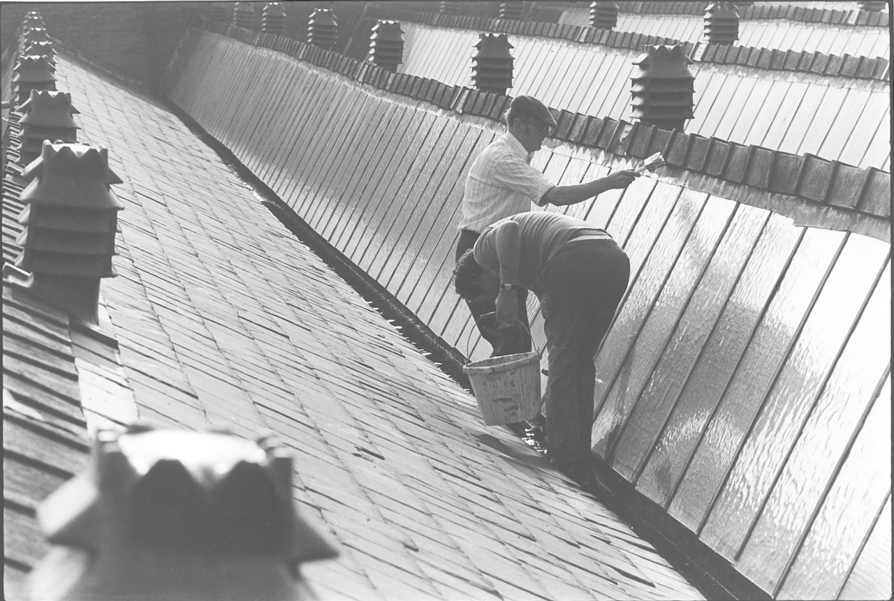
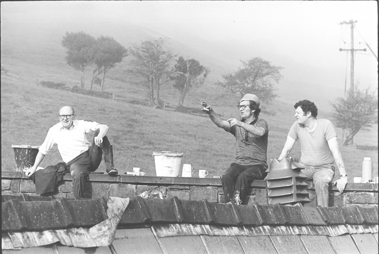
Pictures number 90/91. Negative numbers 786810/7869/18.
This was my favourite annual task. Once a year, the first fine week end in June, we used to whitewash the shed roof windows. In point of fact we were supposed to whitewash the slates and the windows as well but we never whitewashed the slates, we used to whitewash the windows. The idea was to cut down the amount of infra-red radiation getting into the weaving shed through the windows. This wasn’t direct sunlight, it was radiation from the slates which were in direct sunlight. I forget how many windows there were in that roof. I did once count them, I've forgotten how many thousands there are. I did once paint all the lot of them with whitewash in a day by myself and it nearly put my lights out! I think there's twenty odd bays about 250ft long and it's a fair number of windows. But from then on I used my head and got a gang going. On picture 91 they are Ernie Roberts on the left, John Plummer the firebeater telling the tale and Roy Wellock another tackler.
You can see it was a lovely morning, about 05:30, misty and it’s going to be a hot day. Beautiful conditions and a treat to be up there. It took us about three hours. The only problem was the water in the gutters and the sharp edges of the slates nagging at your ankles if you didn’t watch it. Theoretically we were supposed to go up on the roof later in the year to scrub the whitewash off the windows with wire wool but I was crafty, I mixed the whitewash thin and by September it had almost washed off.
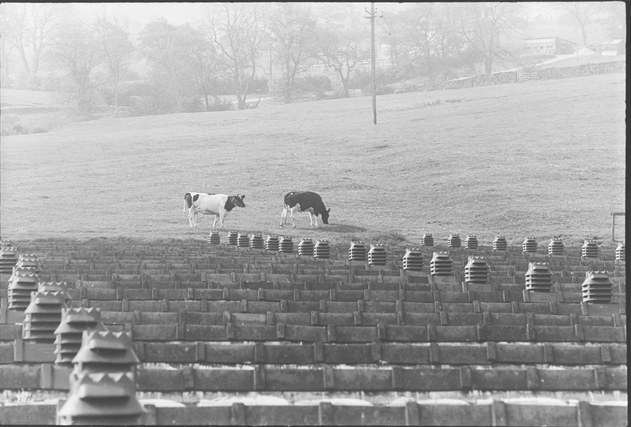
Picture number 92. Negative number 786814.
This is a nice picture that illustrates the old Lancashire saying, ‘One foot in the field and one in the shed’. In the early days of the water-powered industry people worked in agriculture and the textile industry. In summer when water was low and hay harvest was important they worked in the fields, in winter they were in the mill.
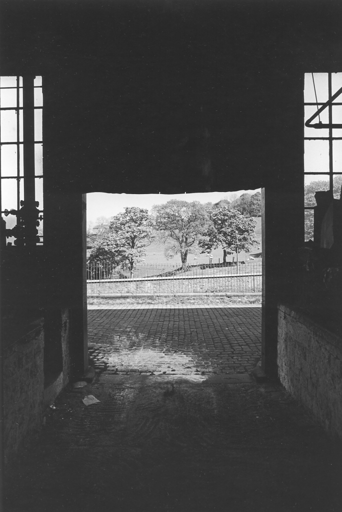
Picture number 93. Negative number 787029.
The same theme repeated. This was the view out of the cart race door in the shed. Dark satanic mill?
At this point in time, May 2nd 1979 this is the last picture in the Bancroft Folio. There may be more pictures of the demolition and scrapping. At the moment it looks as though the mill is going to be razed and everything will go. At the moment all the looms are being scrapped and the shafting cut out of the mill. Obviously I have been following this story through and I shall continue to do so until we are sure what is happening.
That will be the time to finish off this folio and time for me to make my last tape which will be of course a description of the eventual destruction of what was the last steam driven weaving shed in Barlick. I’m getting to the stage in this project now where I can take an overall look at the sort of things that I have been recording. Obviously in a lot of respects I am not really satisfied. I feel that I could have done better. However, without wanting to sound too arrogant I'm not too badly pleased with the way it is shaping up. I think that we are beginning to get a good overall picture and that it what I set out to do.
I wanted to give people in the future a clear overall picture of what it actually felt like, and was like, to work in what is now an obsolete industry. We'll never see the like of it again. We’ll never see investment like this on these sorts of things again in situations like this. The world isn’t geared for it, the world nowadays is geared towards the big multinational corporations. Small units are not complicated units like Bancroft, not in major trades like textiles. The only unit that can pay now in textiles is either a little back street shop or a massive operation involving thousands of people working under the umbrella of one of the big companies. The day of the old cotton manufacturer has gone completely and we'll never see anything like it again. It was, when all was said and done, the beginning of the factory system that we know today. It's history and it's now passing into limbo. All I can say is that I am glad I had the opportunity of being able to do something, however imperfectly it's been done, to record the passing of that industry. However we'll leave the final conclusions and epilogues until we have done the last pictures.
SCG/24 September 2003
7,594 words.
EPILOGUE.
24/09/03 10:08
I have, this day, transcribed the last of the LTP tapes. I have had a celebratory whisky. There is much to yet before the archive is complete but the major task is finished. That is, apart from one last task. I have realised as I did the last transcript that the epilogue was never recorded. Thankfully this means that it hasn’t to be transcribed, I shall just write it.
The first part is the completion of the Bancroft story. The second will be some comments on the project as a whole.
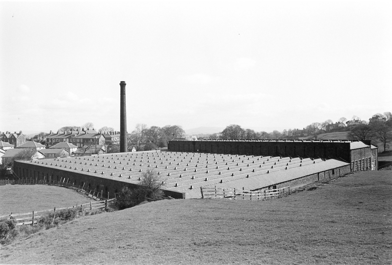
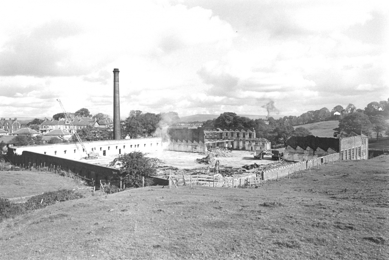
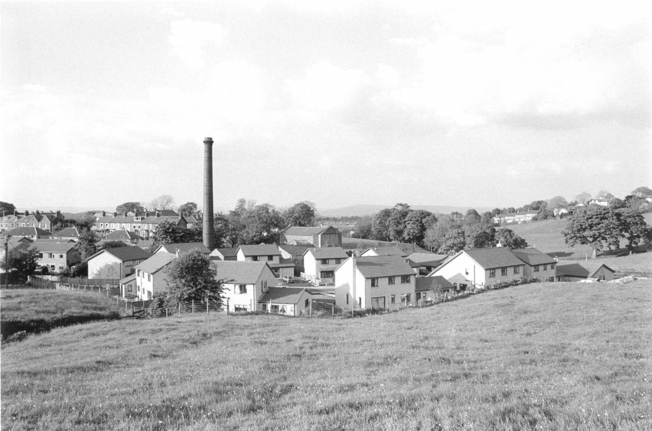
Pictures 94/95/96. Courtesy of Daniel Meadows.
These are three pictures which Daniel Meadows too over a period of four years which encapsulate everything that happened at Bancroft. All the other pictures in the archive have been done by me and Daniel taught me all I know about photography so it is fitting that the last three should be his. They need no explanation, they are Bancroft running, notice the slight haze at the chimney top and the steam coming out of the tape room. Bancroft being demolished by N&R Contractors and Bancroft after the housing estate had been built on the site of the weaving shed.
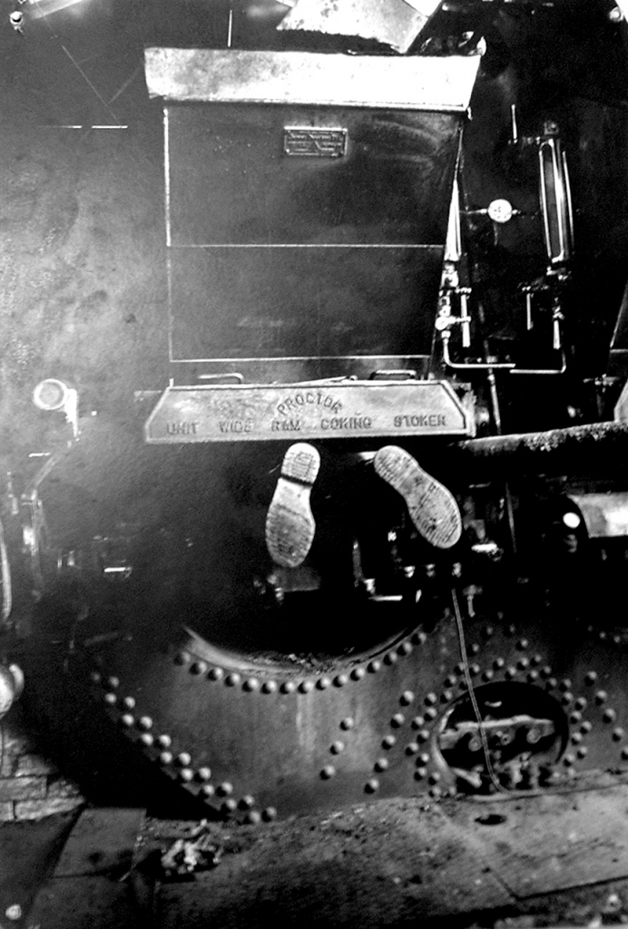
I couldn't resist one more Meadows picture. A bracket on which the ash pit door at the back of the furnace depended broke during the day and at stopping time we had to draw the fires so I could get in the hot box to do the repair. Daniel happened to turn up just as I was working on it and so we have this picture of the engineer. Not recommended, it was quite warm in there!
What transpired after May 1979 was that the mill stood derelict for a while and all negotiations for its sale as a unit collapsed. At the time I taxed Peter White who was Her Majesty’s Inspector of Ancient monuments for North West England about the fate of Bancroft. I wanted the government to buy it, give it a government cloth order at a penny a yard above commercial prices and run it as a heritage site. At the same time I suggested that they buy Brown and Pickles out, move them into the shed and drive their machinery from the engine. B&P could then become a centre of excellence for training young engineers and acting as a contractor for the heritage industry whilst being an attraction in their own right. He said that the government couldn’t enter into a commercial operation and that a decision had been taken to allow Bancroft to be demolished and then they could run screaming down the corridors of power crying rape and get the mill they had set their hearts on, Jubilee Mill at Padiham. In April 1986 N&R Contractors bought Jubilee Mill and demolished it. English Heritage had to take Queen Street Mill at Padiham under their wing eventually and it has never been a success. As I write, its long term future must be open to doubt.
Bancroft Mill then became the subject of a Derelict Land Grant and was demolished apart from the engine house. Pendle Borough stepped in and arranged finance for preserving the engine and boiler house. The firm who had bought Boardman’s out, the original owners, sold the land for housing and left the scene with their money. Discussions started with a view to forming a Trust and running the engine in steam. Whilst all this was going on I was busy elsewhere at Lancaster doing a degree in history as what was laughingly called a ‘mature student’. To tell the truth I had very little interest in Bancroft, I had done what I could to record it, seen a wonderful opportunity squandered and was bruised. I was approached about the Bancroft Trust but said I didn’t want to have anything to do with it. However, a man called Les Say who was the manager of Rolls Royce in Barnoldswick invited me round to his house one evening and persuaded me to join their steering committee. It was a set-up of course and at the first meeting they voted me in as chairman. So, my association with Bancroft continued, I was chairman during the initial setting up of the trust and the start of the refurbishment. I became a Trustee. By this time I was at Lancaster and resigned from the trust as I couldn’t devote enough time to it. I have never held any post with them since but have watched their progress.
The Bancroft Mill Engine Trust still steams the engine regularly and they are an established heritage attraction staffed solely by volunteers. I have nothing but admiration for the way they have kept it going over the years and their future looks bright.
So, the mill and the workers have gone. All that remains is the engine, boiler and chimney. However, thanks to the LTP there is a record of what the engine drove, what went on in the mill and most importantly of the people who lived and died in its service. There is of course the complimentary work on the spinning industry where we did exactly the same exercise in a condenser spinning mill.
CONCLUSION.
I have just allowed myself the luxury of totting up the statistics. Since September 2000 I have re-transcribed 188 transcripts, 1,294,264 words. It doesn’t seem a lot when you say it quickly. There’s an old Jewish rag trade joke that says never mind the quality, feel the width. Well, I’ve done that and it’s impressive. How about the quality? Mr Pirsig said that the best definition of quality was ‘the pursuit of excellence’. Bearing that in mind and looking back at all those words which I have read and re-read more than anyone else will ever do I feel I am allowed an opinion. I believe that this is the best and most comprehensive prime source research that has ever been done on the N E Lancashire steam weaving industry. I hope that future researchers will find it useful. What is certain is that this material comes straight from the workers who did the job. It is their voice and if ever the phrase ‘dignity of labour’ was applicable to anything, it can be used here. What shines through is honest people working in an honest craft and doing the best they could. If I have been able to give them a voice that can echo down the years I am so pleased. They were, and in some cases still are, my friends. Without them I couldn’t have done this. I thank them and I shall never forget them.
I recommend you do the same.

Stanley Challenger Graham, Barnoldswick./24 September 2003
8,639 words.
